Support for Shure AXT400, QLXD4 and ULXD4
V4.1 Supplementary Manual
10
GAIN/PATCH window (1-48, 49-72/ST IN (CL5), 49-64/ST IN
(CL3), ST IN (CL1)) and OVERVIEW window
For Shure AXT400 / QLXD4/ULXD4
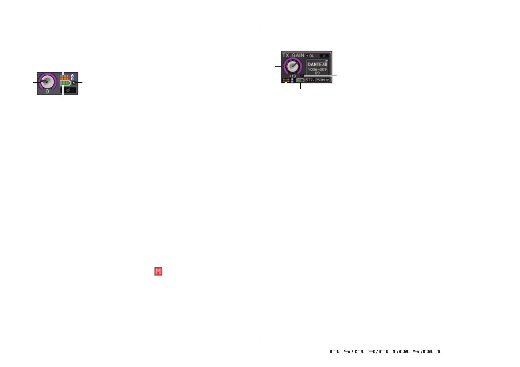
1
TX.GAIN knob (for AXT400)
RX.GAIN knob (for QLXD4/ULXD4)
NOTE
When the AXT400 is connected via a ShowLink® remote control, a gray circle is displayed here
instead of a knob, and the gain cannot be adjusted.
2 RF (Radio Frequency) signal meter
Shows bars to indicate the level of the RF signal (both A and B channels for AXT400).
An active antenna indicator is shown on the right side. It indicates which antenna is
enabled.
NOTE
For details about the relationship between the number of bars and the actual strength of the
signal, refer to the manual from Shure.
3 Battery indicator
Shows bars to indicate the remaining battery power.
NOTE
For details about the relationship between the number of bars and maximum operation time, refer
to the manual from Shure.
4 OL indicator
This will light if the audio signal level of the receiver reaches the overload point.
NOTE
If MUTE is on for the receiver, the MUTE indicator is displayed.
SELECTED CHANNEL window
For Shure AXT400 / QLXD4/ULXD4
1
TX.GAIN knob (for AXT400)
RX.GAIN knob (for QLXD4/ULXD4)
NOTE
When the AXT400 is connected via a ShowLink® remote control, a gray circle is displayed here
instead of a knob, and the gain cannot be adjusted.
2 RF (Radio Frequency) signal meter
Shows bars to indicate the level of the RF signal (both A and B channels for AXT400).
An active antenna indicator is shown on the right side. It indicates which antenna is
enabled.
NOTE
For details about the relationship between the number of bars and the actual strength of the
signal, refer to the manual from Shure.
3 Battery indicator
Shows bars to indicate the remaining battery power.
NOTE
For details about the relationship between the number of bars and maximum operation time, refer
to the manual from Shure.
4 MUTE indicator
Indicates the mute status (on/off) of the audio signal for the receiver.
Precautions
• If the target device is unmounted, the parameters on the console return to their default
values. If a new device is mounted and patched, that device's parameters are applied to the
console.
• All port assignments for a rack are defeated only if the status of the rack is NO ASSIGN.
• Regarding the control of Shure devices, control parameters are not stored in scenes and
saved in console files.
 Loading...