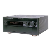
DSP-AX1/RX-V1
DSP-AX1/RX-V1
■ INTERNAL VIEW
q POWER TRANSFORMER
w SUB TRANS P. C. B. (1)
e MAIN P. C. B. (4)
r VIDEO P. C. B. (4)
t VIDEO P. C. B. (1)
y SUB TRANS P. C. B. (5)
u SUB TRANS P. C. B. (3)
i VIDEO P. C. B. (2)
o VIDEO P. C. B. (3)
!0 DSP P. C. B. (1)
!1 MAIN P. C. B. (2)
!2 SUB TRANS P. C. B. (4)
!3 DSP P. C. B. (2)
!4 VIDEO P. C. B. (5)
!5 SUB TRANS P. C. B. (2)
!6 MAIN P. C. B. (3)
!7 MAIN P. C. B. (1)
!8 VIDEO P. C. B. (9)
!9 FUNCTION P. C. B. (1)
q u
!2 !3 !8!4 !6 !7
ow
!1 !5 !9
te r y i !0
■ DISASSEMBLY PROCEDURES (Remove parts in the order as numbered.)
1. Removal of Top Cover
a. Remove 8 screws ( q ) and then slide the Side Panel
to remove it in Fig. 1.
b. Remove 2 screws ( w ) and 2 screws ( e ) and then
remove the Top Cover in Fig. 1.
2. Removal of Bottom Cover
a. Remove 12 screws ( r ) and then remove the Bottom
Cover in Fig. 1.
3. Removal of Front Panel
a. Remove 2 knobs in Fig. 1.
b. Remove 4 screws ( t ) and then slide the Panel/Side
forward to remove it in Fig. 1.
c. Remove 4 screws ( y ) and then remove the Front
Panel in Fig. 1.
Fig. 1
9
q
q
w
e
r
r
r
r
t
t
Bottom Cover
Front Panel
Top Cover
Side Panel
Side Panel
q
q
y
y
Panel/Side
Panel/Side

 Loading...