DSP-AX1/RX-V1
DSP-AX1/RX-V1
Note :
1.When the rear panel has been removed, the ground
wire of the input/output pin jack becomes loose.
Connect it to the chassis by using a lead wire.
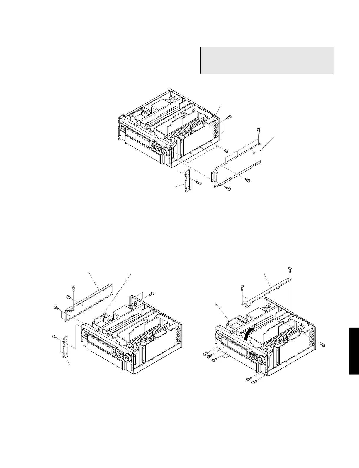
5. Removal of Main P.C.B. (2)
a. Remove 2 screws ( o ) and remove the left Plate
Side in Fig. 3.
a. Remove 6 screws ( !0 ) and then remove the left Side
Frame in Fig. 3.
6. Removal of Main P.C.B. (3)
a. Remove 4 screws ( !1 ) and remove the center Upper
Frame in Fig. 4.
b. Remove 6 screws ( !2 ) and then take up the Sub
Chassis in Fig. 4.
Fig. 2
Fig. 3
Fig. 4
4. Removal of DSP P.C.B. (1)
a. Remove 2 screws ( u ) and remove the right Plate
Side in Fig. 2.
b. Remove 15 screws ( i ) and remove the right Upper
Frame in Fig. 2.
10
i
i
i
i
i
Upper Frame (right)
DSP (1)
!0
!0
!0
!0
Side Frame (L)
MAIN (2)
!2
!2
MAIN (3)
u
Plate Side
(R)
o
Plate Side (L)
!2
!2
!2
!1
!1
!1
Upper Frame
(center)

 Loading...


