DSP-AX1/RX-V1
DSP-AX1/RX-V1
37-1
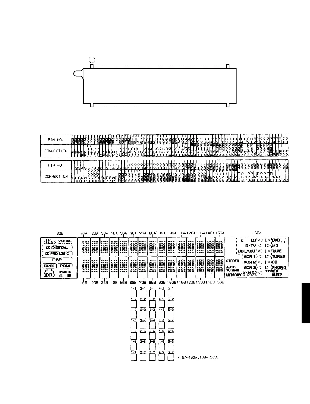
■ DISPLAY DATA
V901 : 32-BT-06G (V4472500)
q^9
&0
PATTERN AREA
13 8
● PIN CONNECTION
● GRID ASSIGNMENT
Note 1) F1, F2 ......... Filament
2) NP .............. No Pin
3) P1A~P35A, P1B~P35B ..... Datum Line
4) 1GA~16GA, 1GB~16GB .............. Grid
5) IC ................ Internal connection
6) Fd terminals are to be supplied through 51kΩ from Ec.
 Loading...


