DSP-AX1/RX-V1
DSP-AX1/RX-V1
37
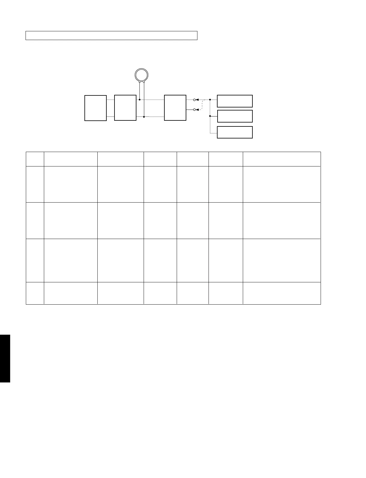
AM Adjustment (This should be done after FM adjustment.)
● Connection Diagram (Measuring instruments)
1) Adjustment of sensitivity
Reception
frequency
1440kHz
* (B-3)
630kHz
* (B-1)
630kHz
* (B-1)
1080kHz
* (B-2)
1440kHz
* (B-3)
Adjustment
point
T2
T2
Signal (ANT IN)
AM ANT
1440kHz
50dBµ
1kHz
30% modulation
AM ANT
630kHz
50dBµ
1kHz
30% modulation
AM ANT
630kHz
1080kHz
1440kHz
30% modulation
AM ANT
60dBµ
Test point
REC OUT
REC OUT
AM ANT
Adjustment item
Adjustment of
sensitivity
(1440Hz)
Verification of
sensitivity
(630kHz)
Verification of
sensitivity
Verification of auto
tuning
Step
1
2
3
4
Rating
Audio output should be
maximized.
Audio output should be
maximized.
Repeat the Step 1 and 2.
Distortion should be 10% or less at
each frequency.
Check to ensure that the voltage at
the ANT terminal is 54dBµ or less.
Auto reception should be avail-
able when the tuning key is moved
UP and DOWN.
See page 34 for TP locations & adjustment points.
*:Execution of PRESET (Refer to page 27.) will facilitate setting reception frequency for adjustment.
GND
AM loop antenna
AM ANT
TUNER
P. C. B .
AM SG
AM SG
ACVM
DIST. M
Oscilloscope
L
R
REC
OUT
 Loading...


