ABCDEFGH
1
2
3
4
5
6
IJK
7
8
DSP-AX1/RX-V1
L
FRONT L
REAR L
CENTER
REAR
CENTER
L
4.9
0.2
0.2
0
0
0
0
0
0
0
0
0
4.2
4.7
4.7
4.7
4.7
4.2
0
0
0
0
0.7
0
0
0
0
0
0
0
0
0
0
0
0
0
0
0
0
00
0
0
0
0
0
0
0
0
0
0
0
0
0
0
0
0
0
0
0
0
0
-11.1
-11.1
-11.1
-11.1
-11.1
-11.1
-11.3
-11.3
-11.1
-11.1
-11.1
-11.1
-11.1
-11.1
-11.3
0.7
0.7
0
0
0
0
0
0
0.7
-11.1
-11.1
-11.1
-11.3
0
4.8
0.7
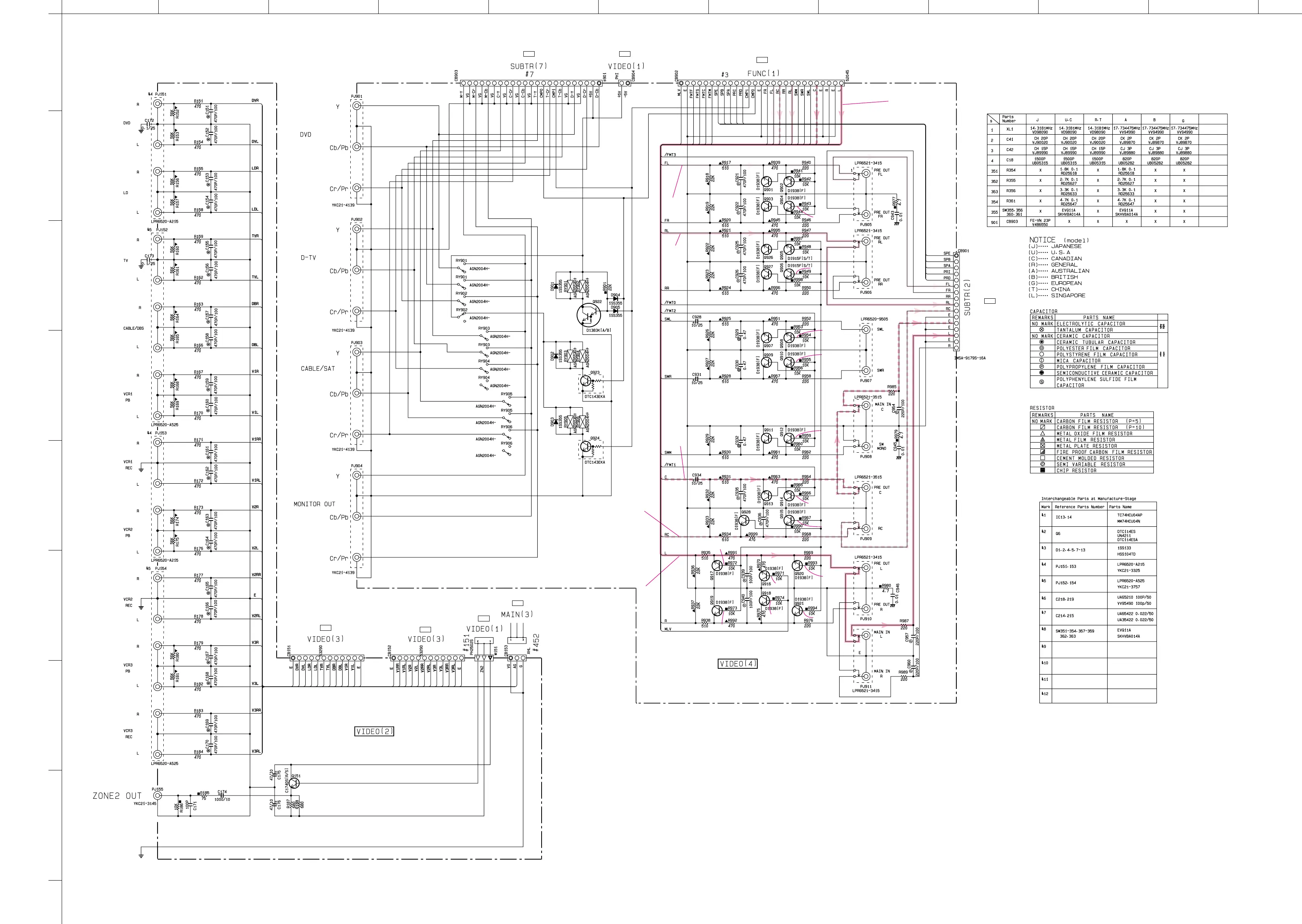
CIRCUIT CHANGES BY MARKET.
X : NOT USED
■ SCHEMATIC DIAGRAM (VIDEO)
* All voltage are measured with a 10MΩ/V DC electric volt meter.
* Components having special characteristics are marked Z and
must be replaced with parts having specifications equal to those
originally installed.
* Schematic diagram is subject to change without notice.
E-96/J-88
P-E97/J89
B-3
P-E97/J89
B-4
P-E95/J87
F-1
P-E93/J85
D-2
P-E99/J91
C-1
P-E95/J87
D-1
P-E92/J84
K-4
P-E98/J90
A-4
 Loading...


