ABCDEFGH
1
2
3
4
5
6
IJKL
7
8
DSP-AX1/RX-V1
11.5
11.5
0
0
0.7
9.7 9.0
9.0
-9.0
-9.0-9.7
0
0
0
0
0
0
0
0
0.7
0
0
0
0
0
-11.5
0
0
-11.5
0
0
0
0
0
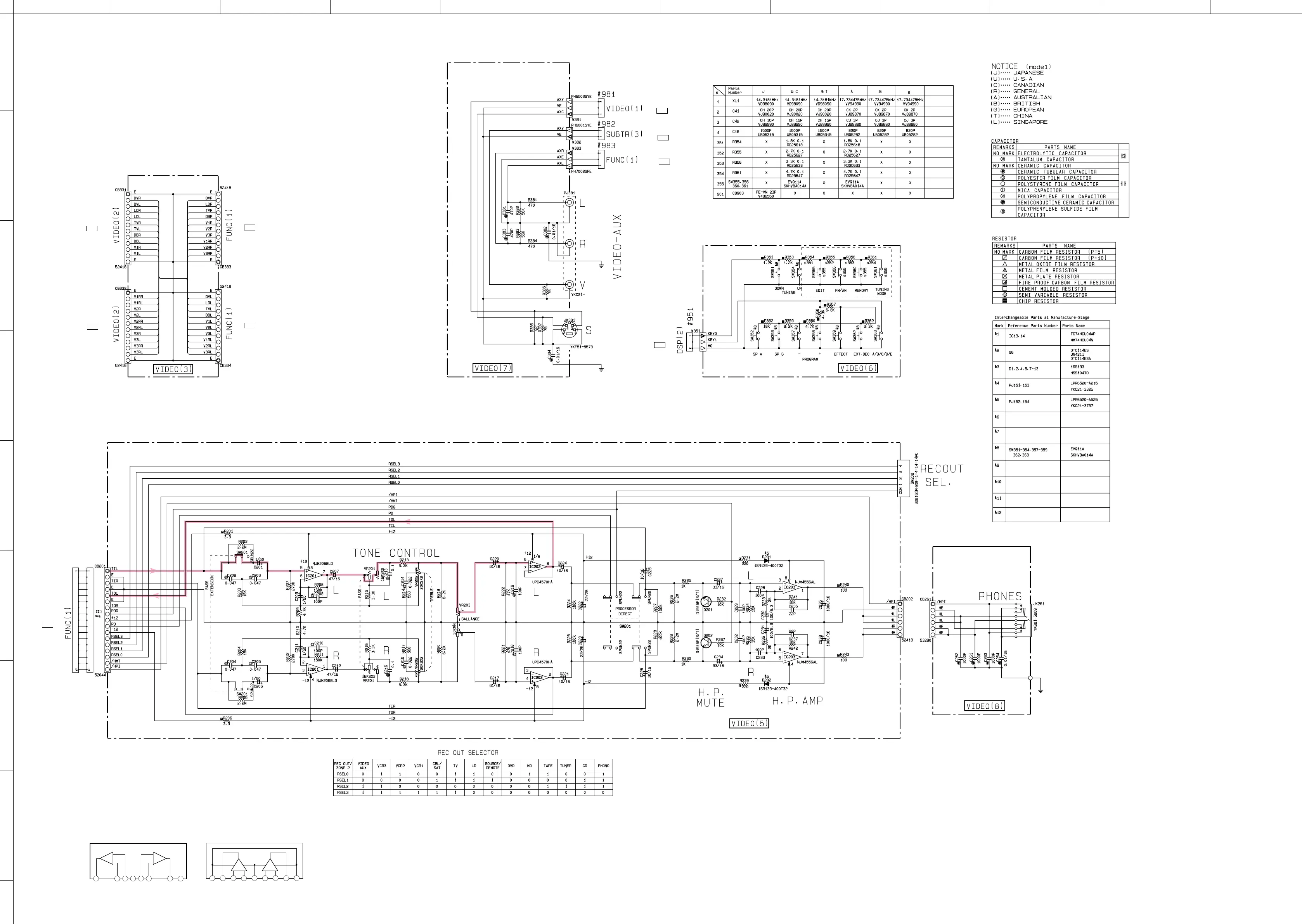
CIRCUIT CHANGES BY MARKET.
X : NOT USED
■ SCHEMATIC DIAGRAM (VIDEO)
* All voltage are measured with a 10MΩ/V DC electric volt meter.
* Components having special characteristics are marked Z and
must be replaced with parts having specifications equal to those
originally installed.
* Schematic diagram is subject to change without notice.
VO1
2
–Vm
1
3
+Vm
1
4
V
EE
5
+Vm
2
6
–Vm
2
7
V
O2
8
V
CC
9
VCC
1
1
– +
– +
2
IC202 : µPC4570HA
Dual OP-Amp
IC201 : NJM2068L-D
IC203 : NJM4556AL
Dual OP-Amp
–IN
1
2
+IN
1
3
–V
CC
4
+IN
2
5
–IN
2
6
OUT
2
7
+V
CC
8
OUT
1
1
–
+
–
+
E-97/J-89
P-E96/J88
C-6
P-E96/J88
D-6
P-E92/J84
B-9
P-E92/J84
D-9
P-E95/J87
C-1
P-E99/J91
F-1
P-E92/J84
C-1
P-E94/J86
I-3
P-E92/J84
H-1
 Loading...


