DSP-AX1/RX-V1
DSP-AX1/RX-V1
51
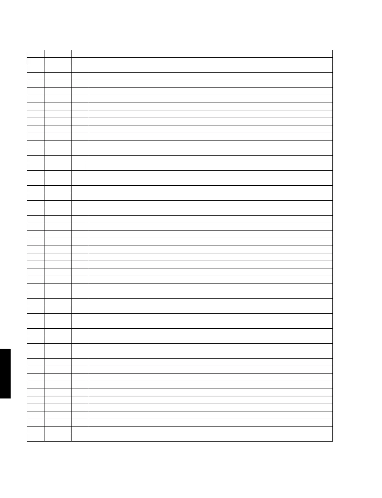
IC24 : PM4007A (P.C.B. DSP)
AC-3 RF Demodulator
No. Name I/O Function
30 A6 O External RAM address output. Address 6
31 A7 O External RAM address output. Address 7
32 GND Ground terminal (0V)
33 VDD +5V power supply
34 A12 O External RAM address output. Address 12
35 A14 O External RAM address output. Address 14 (MSB)
36 WEB O External RAM write enable signal, active at “L”
37 A13 O External RAM address output. Address 13
38 A8 O External RAM address output. Address 8
39 A9 O External RAM address output. Address 9
40 GND Ground terminal (0V)
41 A11 O External RAM address output. Address 11
42 OEB O External RAM output enable signal, active at “L”
43 A10 O External RAM address output. Address 10
44 DB7 I/O External RAM data terminal. Data bus 7
45 DB6 I/O External RAM data terminal. Data bus 6
46 DB5 I/O External RAM data terminal. Data bus 5
47 DB4 I/O External RAM data terminal. Data bus 4
48 DB3 I/O External RAM data terminal. Data bus 3
49 DB2 I/O External RAM data terminal. Data bus 2
50 DB1 I/O External RAM data terminal. Data bus 1
51 DB0 I/O External RAM data terminal. Data bus 0
52 VDD +5V power supply
53 GND Ground terminal (0V)
54 TI1 I IC test terminal, normally connected to VDD
55 VIN I VCXO input
56 VOUT O VCXO output
57 TI2 I IC test terminal, normally connected to GND (or unconnected)
58 TI3 I IC test terminal, normally connected to GND (or unconnected)
59 TLDB I IC test terminal, normally connected to GND (or unconnected)
60 TCK I IC test terminal, normally connected to GND (or unconnected)
61 TRP O Output terminal for IC test
62 TDO O Output terminal for IC test
63 PDO O Output terminal for phase comparator (tri-state)
64 TI4 I IC test terminal, normally connected to GND (or unconnected)
65 PDDIS I Input terminal to control PDO output. Output ON at “L”
66 MUTO O Muting output. Muting available at “H”. Setting becomes “H” when “MUTI=H” or AC-3 is asynchronous.
67 TI5 I IC test terminal, normally connected to GND (or unconnected)
68 VLDY O Output terminal for IC test
69 DASYO O Output terminal for IC test
70 DAOUT O Digital out output (serial data stream output)
71 DAIN I Digital external input, through to DAOUT when DASEL is “H”.
72 DASEL I Digital out select
73 TI8 I IC test terminal, normally connected to GND (or unconnected)
74 C2F1 O Terminal used to indicate error condition after C2 correction, whether completely corrected or not.
75 C2F0 O Terminal used to indicate error condition after C2 correction, number of errors at C2.
76 C1F1 O Terminal used to indicate error condition after C1 correction, whether any error exists at C1 or not.
77 C1F0 O Terminal used to indicate error condition after C1 correction, number of errors at C1.
78 MUTI I Muting input. Muting available at “H”
79 VDD +5V power supply
80 GND Ground terminal (0V)

 Loading...


