GENERATOR SYSTEM I
ELEC
I u I
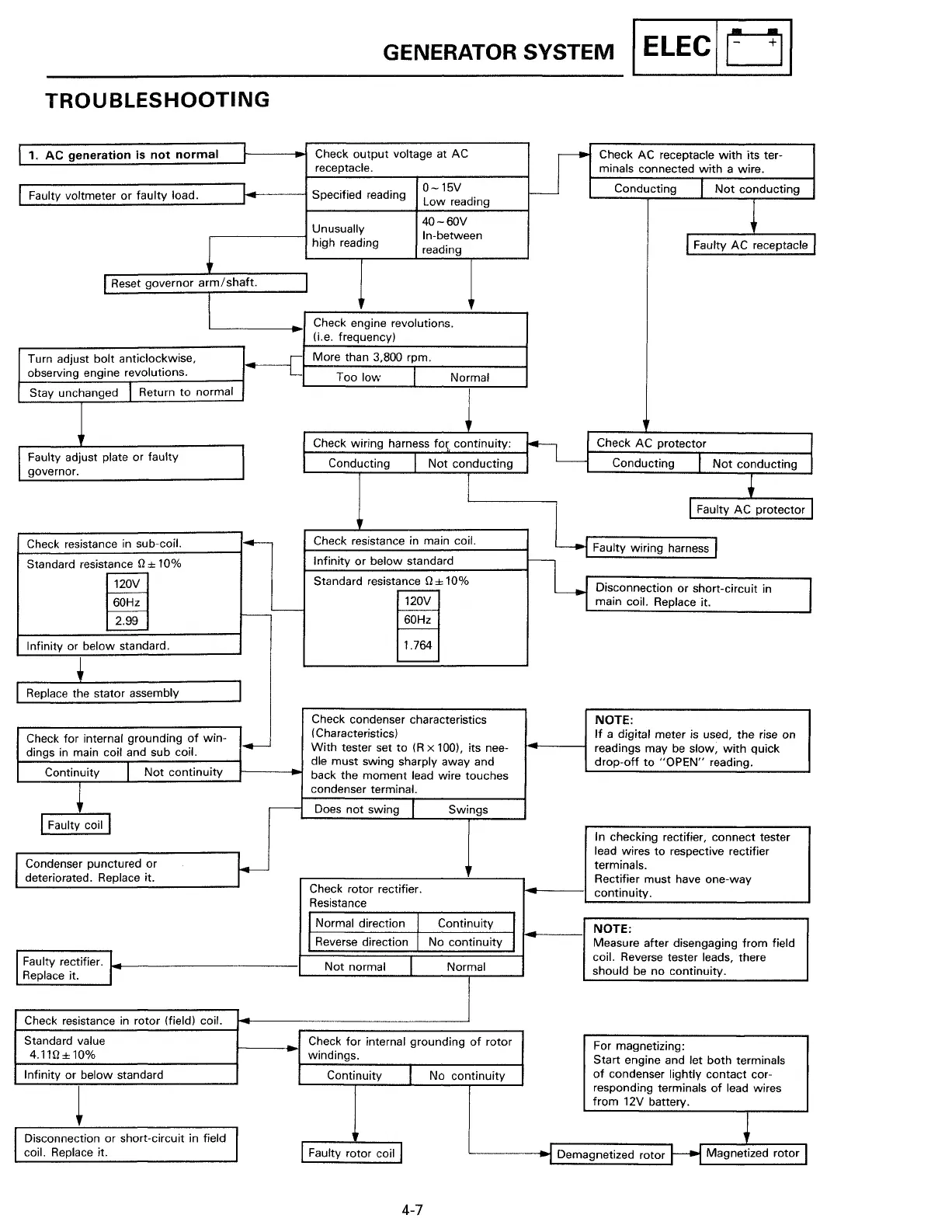
TROUBLESHOOTING
1.
AC
generation
is
not
normal
Check
output
voltage at AC
Lr
Check AC receptacle
with
its ter-
receptacle.
minals connected
with
a wire.
0-15V
Conducting
I
Faulty voltmeter
or
faulty
load.
Specified reading
Not
conducting
Low
reading
~
Unusually
40-60V
In-between
~
high reading
reading
l Faulty
AC
receptacle
Reset governor
arm/
shaft.
I
Check engine revolutions.
(i.e. frequency)
Turn adjust
bolt
anticlockwise,
r
More than 3,800 rpm.
observing engine revolutions.
L
Too
low
Normal
Stay unchanged
I Return
to
normal
l
Check wiring harness
fo~
continuity:
Check
AC
protector
Faulty adjust plate or faulty
Conducting
Not
conducting
Conducting
I
Not
conducting
governor.
•
l Faulty
AC
protector
1--
Check resistance in main coil.
~~
Faulty wiring harness I
Check resistance
in
sub-coil.
Infinity
or
below standard
Standard resistance
fl
± 10%
Standard resistance
fl
± 10%
120V
11--r
o;=oooc<;oo"'
•hort-ok'";'
;,
f.---
..---
60Hz
120V
main coil. Replace it.
f-----
1---L,__
I--
~
60Hz
1---
Infinity or below standard.
1.764
+
I
Replace the stator assembly
I
Check condenser characteristics
NOTE:
Check
for
internal grounding
of
win-
(Characteristics)
If
a digital meter
is
used, the rise on
dings
in
main coil and sub coil.
,
__
With
tester set
to
(R
x 100), its nee-
readings may
be
slow,
with
quick
I
Not
continuity
die must swing sharply away and
drop-off
to
"OPEN"
reading.
Continuity
back the
moment
lead wire touches
~
condenser terminal.
r--
Does
not
swing
Swings
I Faulty coil I
In checking rectifier, connect tester
lead wires
to
respective rectifier
Condenser punctured
or
~
terminals.
deteriorated. Replace it.
Check rotor rectifier.
Rectifier must have one-way
continuity.
Resistance
I Normal direction Continuity
I
NOTE:
I Reverse direction
No
continuity
I
Measure after disengaging
from
field
I Faulty rectifier.
I·
coil. Reverse tester leads, there
Not
normal
Normal
should be no continuity.
Replace it.
Check resistance
in
rotor (field) coil.
Standard value
Check
for
internal grounding
of
rotor
For magnetizing:
4.11fl±10%
windings.
Start
engine and let
both
terminals
Infinity
or
below standard
Continuity
I
No
continuity
of
condenser lightly
contact
cor-
t
responding terminals
of
lead wires
from
12V battery.
i
Disconnection or short-circuit in field
coil. Replace it.
Faulty rotor coil
I
Demagnetized rotor
Magnetized rotor
4-7
 Loading...