En 24
Connecting to the jack on the front panel
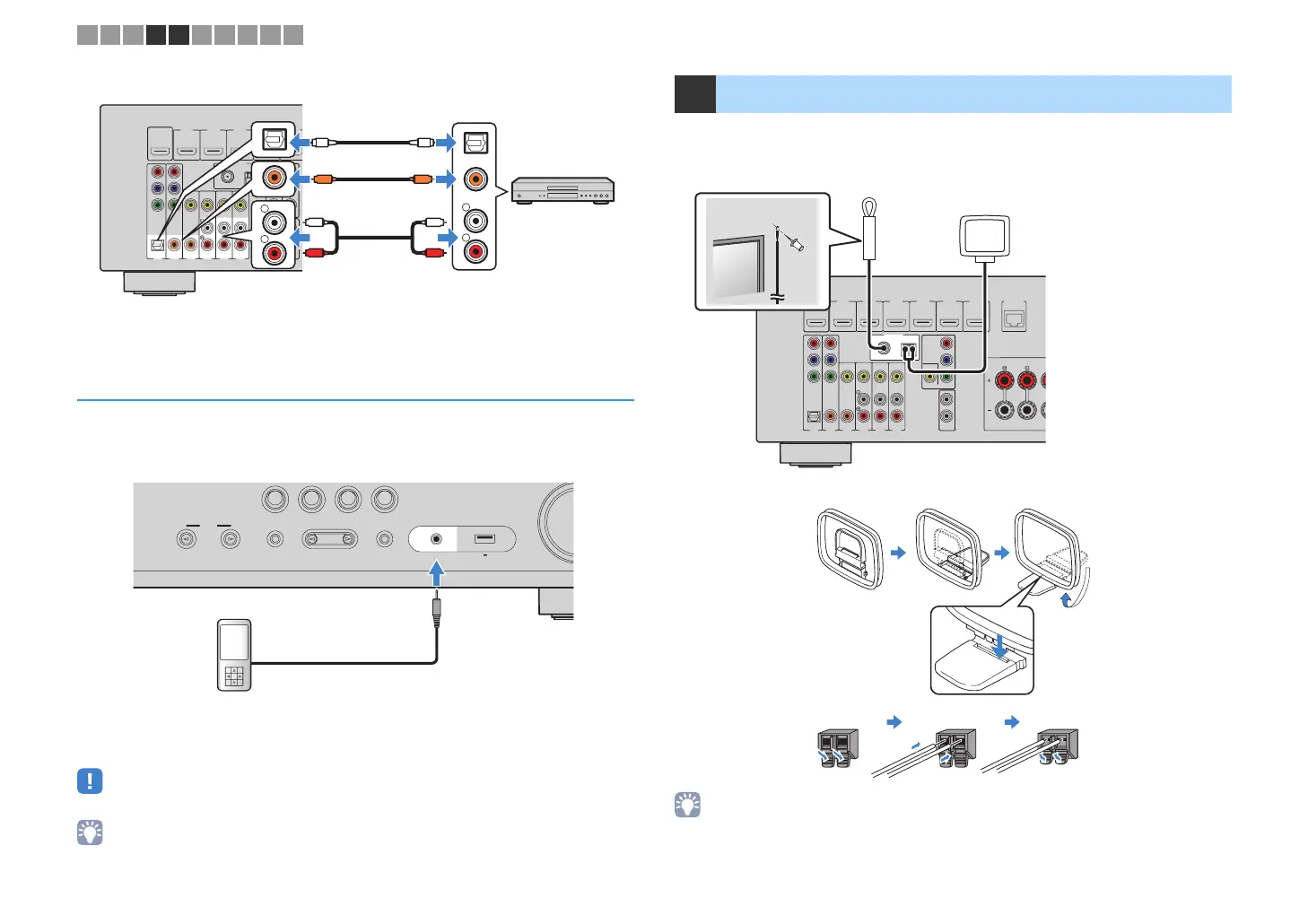
Use the AUX jack on the front panel to temporarily connect devices such as portable
audio players to the unit.
Before making a connection, stop playback on the device and turn down the volume on the unit.
If you select “AUX” as the input source by pressing INPUT, the audio played back on
the device will be output from the unit.
• You need to prepare the audio cable that matches the output jacks on your device.
• For details on how to connect an USB storage device, see “Connecting a USB storage device” (p.59).
Connect the supplied FM/AM antennas to the unit.
Fix the end of the FM antenna to a wall, and place the AM antenna on a flat surface.
Assembling and connecting the AM antenna
• Unwind only the length of cable needed from the AM antenna unit.
• The wires of the AM antenna have no polarity.
OPTICAL
(TV)
COAXIAL
COAXIAL
VIDEO
COMPONENT
VIDEO
Y
P
B
P
R
FM
AM
75Ω
ANTENNA
(RADIO)
COMPONENT
VIDEO
VIDEO
MONITOROUT
Y
1
2
SUBWOOFER
PREOUT
HDMI2
HDMI3
HDMI4
HDMI5
HDMI1
(BD/DVD)
HDMIOUT
HDCP2.2
ARC
P
B
P
R
AV4
AV3
AV6
AV5
AV2
AV1
R
L
COAXIAL
OPTICAL
R
L
COAXIAL
OPTICAL
CC
L
R
L
R
OO
Audio output
(either digital optical,
digital coaxial, or analog stereo)
(RX-V579)
AV 1-6 jacks
(RX-V479)
AUDIO 1-2 jacks
AV 1-4 jacks
The unit (rear)
Audio device
PROGRAM
TONE CONTROL
STRAIGHT
(CONNECT)
AUX
AUDI O
5V 1A
INPUT
TV
BD
DVD
NET
RADIO
Portable audio player
The unit (front)
5 Connecting the FM/AM antennas
OPTICAL
(TV)
COAXIAL
COAXIAL
VIDEO
COMPONENT
VIDEO
Y
P
B
P
R
FM
AM
75Ω
ANTENNA
(RADIO)
COMPONENT
VIDEO
VIDEO
MONITOROUT
Y
1
2
SUBWOOFER
PREOUT
HDMI2
HDMI3
HDMI4
HDMI5
HDMI6
HDCP2.2
HDMI1
(BD/DVD)
HDMIOUT
HDCP2.2
ARC
N
ETWORK
(NET)
FRONT
P
B
P
R
AV4
AV3
AV6
AV5
AV2
AV1
FM antenna
AM antenna
The unit (rear)
Hold down Insert Release
1 2 3 4 5 6 7 8 9 10
00_RX-V479_V579_om_U.book Page 24 Wednesday, March 25, 2015 9:59 AM
 Loading...