RX-V357/HTR-5830
27
RX-V357/HTR-5830
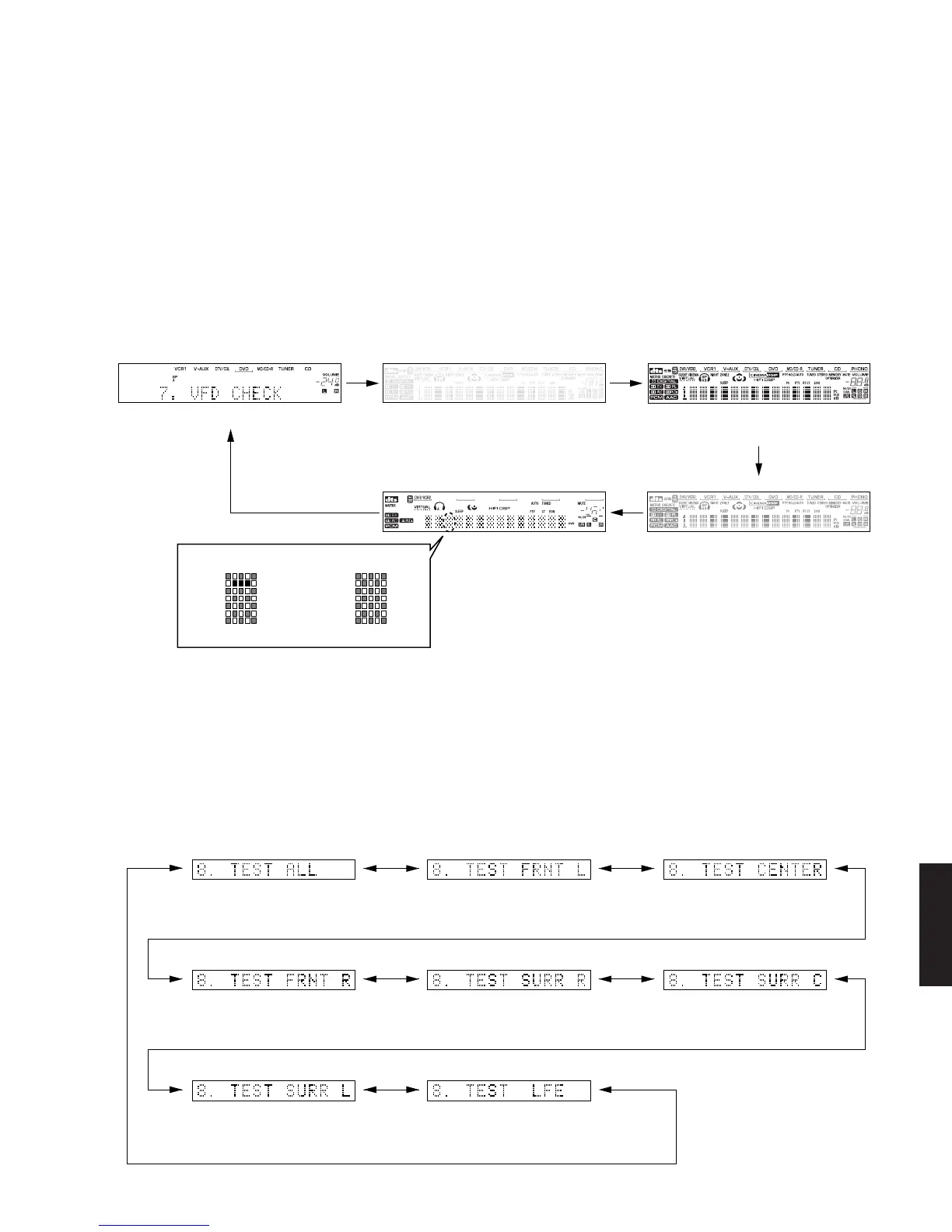
Initial display / All segments OFF / All segments ON (dimmer 100%) /
All segments ON (dimmer 50%) /
Lighting of segments
in lattice /
Lighting in lattice /
Normal / Short /
Segment conditions of the FL driver and the FL tube are
checked by turning ON and OFF all segments. Next, the
operation of the FL driver is checked by using the dimmer
control. Then a short between segments next to each
other is checked by turning ON and OFF all segments
alternately (in lattice). (In the example below, the
segments in the second row from the top are shorted.)
7. DISPLAY CHECK
This program is used to check the FL display section. The
display condition varies as shown below according to the
sub-menu operation. The signals are processed using
EFFECT OFF (The L/R signal is output using ANALOG
FRONT BYPASS.)
Regarding internal/external synchronization selection of
the image signals by the microprocessor control, the
internal synchronization is selected when the initial display
is provided and when all FL's light up and the external
synchronization at any other time.
Also, except when the initial display is provided, 128
characters for confirmation of the OSD driver are
displayed as the image output.
8. MANUAL TEST
The noise generator built into the DSP outputs the test
noise through the channels specified by the sub-menu.
The noise frequency for LFE is 35 to 250 Hz. Other than
that, the center frequency is 800Hz.
TEST ALL TEST FRONT L TEST CENTER
TEST FRONT R
TEST SURROUND R TEST SURROUND C
TEST SURROUND L
Noise is output from all channels. Noise is output from the FRONT L
channel.
Noise is output from the CENTER
channel.
Noise is output from the FRONT R
channel.
Noise is output from the SURROUND L
channel.
TEST LFE
Noise is output from the SUB WOOFER
channel.
Noise is output from the SURROUND R
channel.
Not applied to these models.
 Loading...