19
MG82CX/MG102C
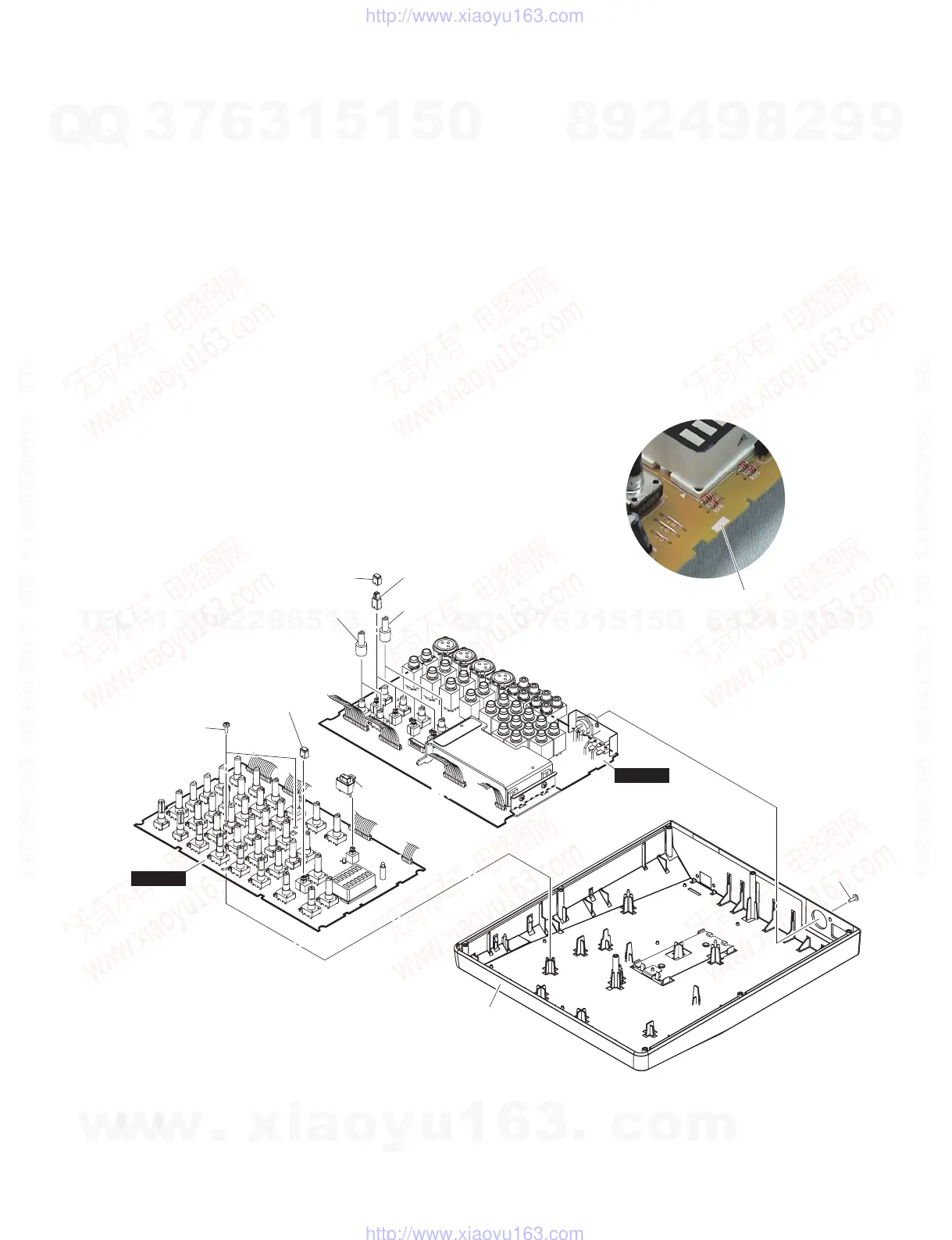
Bottom case assembly
(ボトムケースAssy)
MAIN10 MAIN
MAIN10 JACK
Push button HPF
(ボタンHPF)
Knob joint HPF
(ノブ継ぎ手HPF)
Push button HPF
(ボタンHPF)
Knob joint VRS
(ノブ継ぎ手VRS)
Knob joint VRS
(ノブ継ぎ手VRS)
[163B]
[100]
Push button PFL
(ボタンPFL)
Push button PFL
(ボタンPFL)
(MAIN10 シートの引っ掛け位置)
Engagement points on the MAIN10 circuit board
2-3 MAIN10 シートからノブ継ぎ手、ボタンを外しま
す。(図 2)
※ ノブ継ぎ手とボタンは MAIN10 シートの構成部
品ではありません。MAIN10 シートを交換する場
合は、ノブ継ぎ手とボタンを取り外して新しい
MAIN10 シートに取り付けてください。(図 2)
※ MAIN10 シートを取り付けるときは、ボトムケー
ス Ass'y にある 7 個所のツメに MANI10 シートが
引っ掛かるように取り付けてください。(写真 1)
Fig.2( 図 2)
[100]:BindHeadTappingScrew-B(B タイト+ BIND)3.0X8MFZN2W3(WE774300)
[163]:BindHeadTappingScrew-B(B タイト+ BIND)3.0X8MFZN2B3(WE774400)
2-3 Remove the knob joints and push buttons from the
MAIN10 circuit board. (Fig. 2)
* The knob joints and push buttons are not com-
ponents of the MAIN10 circuit board. When
replacing the MAIN10 circuit board, remove the
knob joints and push buttons and install them
on the new MAIN10 circuit board. (Fig. 2)
* When installing the MAIN10 circuit board, fit
the seven (7) claws on the bottom case assem-
bly to the MANI10 circuit board. (Photo 1)
Photo1( 写真 1)
w
w
w
.
x
i
a
o
y
u
1
6
3
.
c
o
m
Q
Q
3
7
6
3
1
5
1
5
0
9
9
2
8
9
4
2
9
8
T
E
L
1
3
9
4
2
2
9
6
5
1
3
9
9
2
8
9
4
2
9
8
0
5
1
5
1
3
6
7
3
Q
Q
TEL 13942296513 QQ 376315150 892498299
TEL 13942296513 QQ 376315150 892498299
http://www.xiaoyu163.com
http://www.xiaoyu163.com
 Loading...