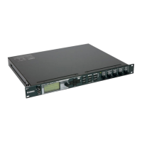
MG82CX/MG102C
36
* For the signal path o, check only the ST OUT R.
* For the signal paths !1 and !2, check only the MONITOR OUT L, R.
2-14 Maximum output
Under 2-2 setting, input the signal to the MIC INPUT of CH1.
Check that the distortion is 1.0% or less when the output level of the ST OUT L, R, EFFECT SEND (AUX SEND in
case of MG102C), and MONITOR OUT L, R is set to +20.0 dBu.
Check that the distortion is 1.0% or less when the output level at the PHONES L, R is set to +7.5 dBu.
* Turn the PAN (PAN/BAL, BAL) control clockwise or counterclockwise fully.
* Set the CH level controls other than CH1 to Minimum.
2-15 Equivalent input noise
Under 2-2 setting, check that the noise level at the ST OUT L is –52.0 dBu or less when the 2 pin and 3 pin of the CH
INPUT MIC are connected with the resistor of 150 ohms.
If the noise level is –52.0 dBu or more, check that the equivalent input noise level is –128.0 dBu or less.
Check that the noise level at the ST OUT L is –44.0 dBu or less when the 2 pin and 3 pin of the ST CH INPUT MIC
are connected with the resistor of 150 ohms.
If the noise level is –44.0 dBu or more, check that the equivalent input noise level is –120.0 dBu or less.
* [Equivalent input noise level] = [Noise level] – [Channel gain]
* Set the CH level controls other than the measurement channel to Minimum.
* Use the 12.7 kHz, –6 dB/octave Low Pass Filter when measuring the noise level.
2-16 Residual noise
Under 2-2 setting, set the channel level controls of all the inputs to Minimum.
Check that the noise level at each output terminal is not more than the values shown in Table 2-16-1 when the
MASTER volume is set to Maximum and Minimum.
* Set the STEREO level control to Minimum when measuring at the MONITOR OUT L, R and PHONES L, R.
* Use the 12.7 kHz, –6 dB/octave Low Pass Filter when measuring the noise level.
2-17 Compressor
2-17-1 Gain
Under 2-2 setting, check that the output level at the INSERT OUT 1, 2 is within the range shown in Table 2-17-1 when
the COMP controls for the CH1 and CH2 are set to Maximum.
2-17-2 Ratio
Check that the output level at the INSERT OUT 1, 2 is within the range shown in Table 2-17-2 compared with the
output level in Table 2-17-1 when the input level is raised by 10.0 dB.
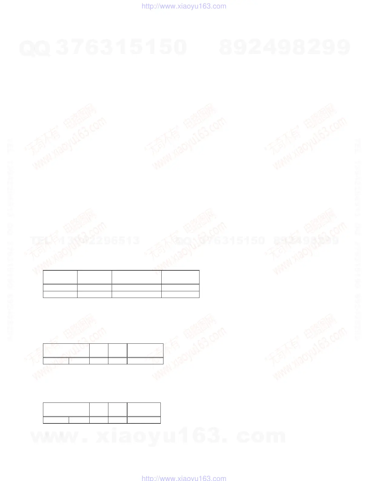
Table 2-16-1
MASTER
volume
ST OUT
(L, R)
EFFECT SEND (MG82CX)
AUX SEND (MG102C)
MONITOR OUT
(L, R)
MAX –81.0 dBu –85.0 dBu –78.0 dBu
MIN –100.0 dBu — –93.0 dBu
Table 2-17-1
INPUT
Input
level
COMP
control
INSERT OUT
(1, 2)
MIC 1,2
–65.0 dBu Maximum +3.0 dBu ± 2.0 dB
Table 2-17-2
INPUT
Input
level
COMP
control
INSERT OUT
(1, 2)
MIC 1,2
–55.0 dBu Maximum +3.3 dBu ± 1.0 dB
w
w
w
.
x
i
a
o
y
u
1
6
3
.
c
o
m
Q
Q
3
7
6
3
1
5
1
5
0
9
9
2
8
9
4
2
9
8
T
E
L
1
3
9
4
2
2
9
6
5
1
3
9
9
2
8
9
4
2
9
8
0
5
1
5
1
3
6
7
3
Q
Q
TEL 13942296513 QQ 376315150 892498299
TEL 13942296513 QQ 376315150 892498299
http://www.xiaoyu163.com
http://www.xiaoyu163.com
 Loading...