MG82CX/MG102C
34
2-7 Frequency characteristics
For the signal paths q to !2 (excluding e, y, and u) in Tables 2-6-1 to 2-6-6, check that the output level at each
output terminal when the signal frequency is set to 20 Hz and 20 kHz is within the range of +1.0/–2.5 dB compared
with output level when the signal frequency is set to 1 kHz.
* Check that the output level is within the range of +1.0/–4.5 dB when the GAIN control is at Maximum and the signal
frequency is set to 20 Hz.
* For the signal path q, check the ST OUT L, R and EFFECT SEND (AUX SEND in case of MG102C) when the
signal is input to CH1, and check only the ST OUT L when the signal is input to CH2.
* For the signal paths r to o, check only the ST OUT L or ST OUT R.
* For the signal paths !1 and !2, check only the MONITOR OUT L, R and PHONES L, R.
2-8 High pass fi lter
Under 2-2 setting, input the signal of –36.0 dBu, 80 Hz to the MIC INPUT and turn on the
80
switches of CH1 to
CH5/6.
Then, check that the output level at the ST OUT L is within the range shown in Table 2-8-1 compared with the level
when the switch is off.
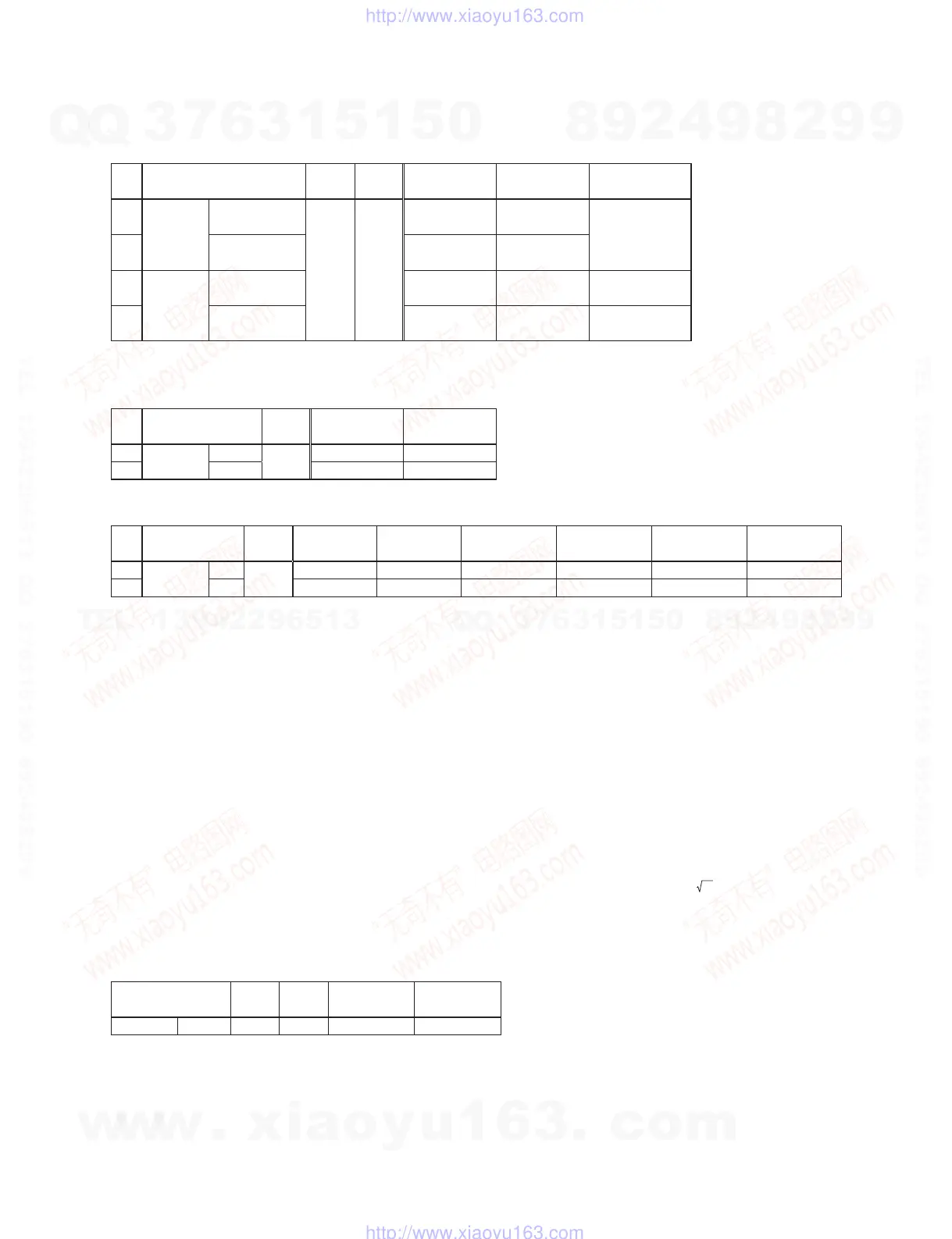
Table 2-6-4 ST CH INPUT (CH7/8, CH9/10: MG102C)
INPUT
Input
level
GAIN
control
ST OUT L ST OUT R
EFFECT SEND (MG82CX)
AUX SEND (MG102C)
⑧
PHONE
(LINE)
7 L
9 L (MG102C)
–22.0 dBu
—
+4.5 dBu ± 2.0 dB
—
+1.5 dBu ± 2.0 dB
⑨
8 R
10 R (MG102C)
—
+4.5 dBu ± 2.0 dB
PIN
(LINE)
7 L
9 L (MG102C)
+4.5 dBu ± 2.0 dB
——
8 R
10 R (MG102C)
—
+4.5 dBu ± 2.0 dB
—
Table 2-6-5 EFFECT RETURN (MG82CX) (L/MONO, R)
AUX RETURN (MG102C) (L/MONO, R)
INPUT
Input
level
ST OUT L ST OUT R
⑩
PHONE
(LINE)
L/MONO
–8.0 dBu
+3.5 dBu ± 2.0 dB +3.5 dBu ± 2.0 dB
R—
+3.5 dBu ± 2.0 dB
Table 2-6-6 2TR IN (L, R)
INPUT
Input
level
ST OUT L ST OUT R
MONITOR
OUT L
MONITOR
OUT R
PHONES L PHONES R
⑪
PIN
(LINE)
L
–35.8 dBu
–12.5 dBu ± 2.0 dB
—
–2.0 dBu ± 2.0 dB *3
—
–13.5 dBu ± 2.0 dB *3
—
⑫
R—
–12.5 dBu ± 2.0 dB
—
–2.0 dBu ± 2.0 dB *3
—
–13.5 dBu ± 2.0 dB *3
* Set the 2TR IN level control to Maximum when measuring for Table 2-6-6.
*3 Turn on the TO STEREO/TO MONITOR switch (TO MONITOR setting).
Table 2-8-1
INPUT
Input
level
GAIN
control
Input
frequency
ST OUT L
MIC 1–5/6
–36.0 dBu Minimum
80 Hz
–3.0 dBu ± 2.0 dB
* Set the GAIN control to Minimum.
w
w
w
.
x
i
a
o
y
u
1
6
3
.
c
o
m
Q
Q
3
7
6
3
1
5
1
5
0
9
9
2
8
9
4
2
9
8
T
E
L
1
3
9
4
2
2
9
6
5
1
3
9
9
2
8
9
4
2
9
8
0
5
1
5
1
3
6
7
3
Q
Q
TEL 13942296513 QQ 376315150 892498299
TEL 13942296513 QQ 376315150 892498299
http://www.xiaoyu163.com
http://www.xiaoyu163.com
 Loading...