4-12
SPEC
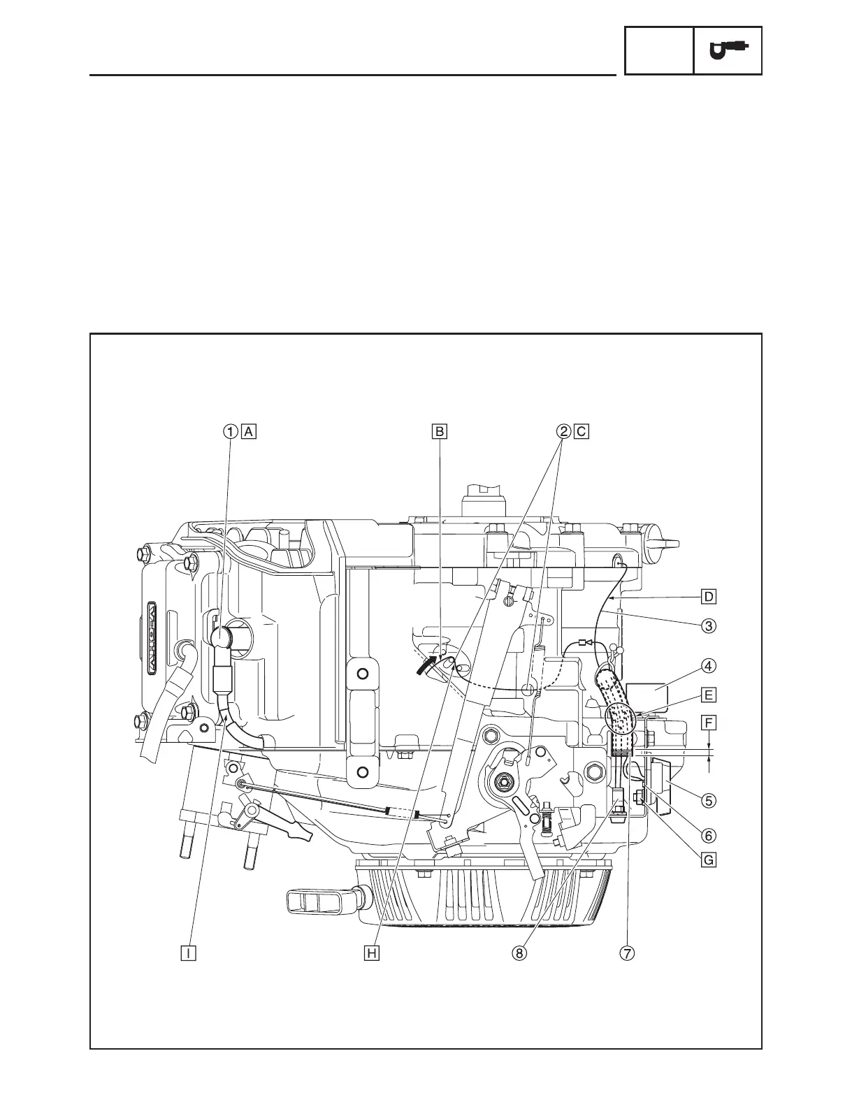
WIRE ROUTING DIAGRAM
WIRE ROUTING DIAGRAM
UPPER SIDE VIEW
1 Spark plug cap
2 TCI unit lead
3 Oil level switch lead
4 Oil warning unit
5 Engine switch
6 Engine switch lead (ground)
7 Wire harness protector
8 Oil warning light
A
The spark plug cap should
face the direction indicated in
the illustration.
B
After passing the lead through,
lightly pull it in the direction of
the arrow. Make sure there is
no excessive slack in the lead
inside the fan case.
C
Route the TCI unit lead as shown.
D
The lead is black and the pro-
tector is gray.
E
Pass through the leads to the
wire harness protector, and
then push into the oil warning
unit towards back.
F
Make sure that the gap
between the end of the wire
harness protector and end of
the crankcase is 5 mm (0.2 in)
or more.
G
Fasten the ground terminal
and engine switch together.
H
Insert the lead all the way in.
I
Screw in the high tension cord
until it touches the spark plug
cap.
7HC-F8197-11.indb 12 2015/09/01 14:08:24