4-13
SPEC
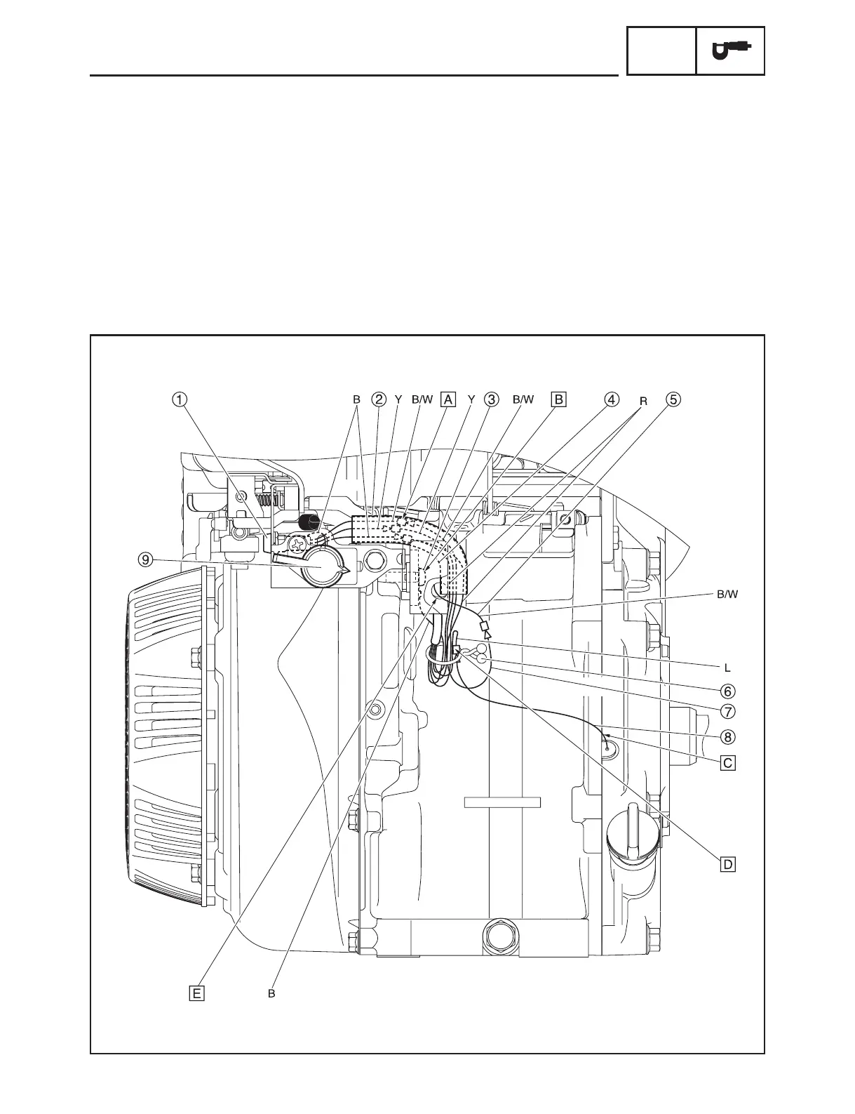
WIRE ROUTING DIAGRAM
ENGINE SWITCH AND OIL WARNING UNIT
1 Oil warning light
2 Wire harness protector
3 Oil warning unit lead (ground)
4 Oil warning unit
5 TCI unit lead
6 Clamp
7 Oil warning unit lead
8 Oil level switch lead
9 Engine switch
A
Pass through the leads to the
wire harness protector, and
then push into the oil warning
unit towards back.
B
Fasten the ground terminal
and oil warning unit together.
C
The lead is black and the pro-
tector is gray.
D
Fasten the connector area
using the clamp.
E
Pass the TCI unit lead through
hole in the crankcase.
Color code
B .........Black
L..........Blue
R .........Red
Y .........Yellow
B/W .....Black/White
7HC-F8197-11.indb 13 2015/09/01 14:08:25