Rear panel 11
MX400 User’s Guide
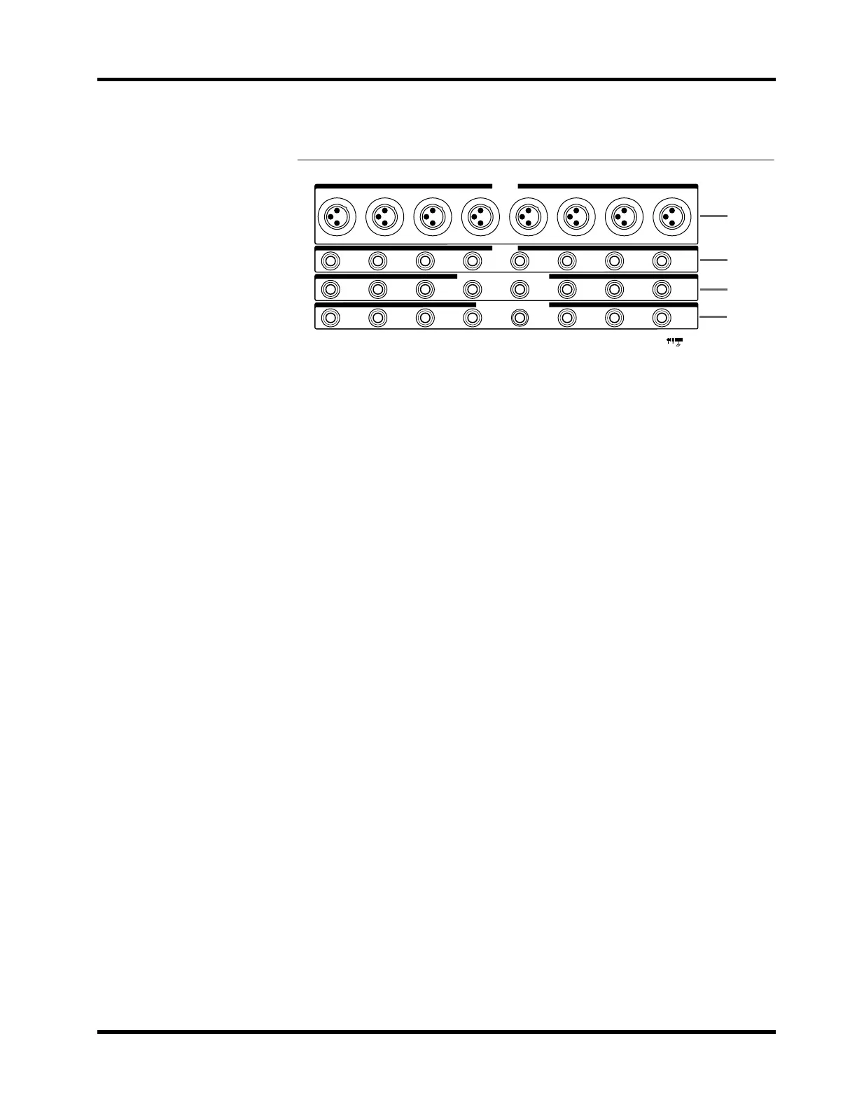
Rear panel
1 INPUT A jacks
These are unbalanced XLR3-31 type jacks which input the signal for each
input module. Use the A/B switch to select these jacks.
• Nominal input level: –60dB
Phantom power (+48 V) can be supplied to these jacks. Phantom power is
turned on/off using the PHANTOM switch.
When the PHANTOM switch is on, make sure that those devices which do
not require phantom power are connected to the INPUT B jacks (
2).
2 INPUT B jacks
These are 1/4” phone jacks which input the signal for each input module.
Use the A/B switch to select these jacks. These are balanced TRS jacks, with
tip=hot, ring=cold, and sleeve=ground.
• Nominal input level: –60dB
3 INPUT INSERT I/O jacks (0dB)
These are 1/4” phone jacks patched in front of the input module faders.
These are unbalanced TRS jacks, with tip=out, ring=in, and sleeve=ground.
• Nominal input level: 0dB
• Nominal output level: 0dB
4 DIRECT OUT jacks (0dB)
These are unbalanced 1/4” phone jacks which output the post-fader signal
independently from each input module.
• Nominal output level: 0dB
INSERT
OUT IN
87654321
87654321
87654321
87654321
DIRECT OUT 0dB
INSERT I/O 0dBINPUT
INPUT B
INPUT A
1
2
3
4