EasyManua.ls Logo

Yamaha P-85 Service Manual

Yamaha P-85
75 pages
To Next Page IconTo Next Page
Page #1 background imageLoading...
Page #1 background image
SERVICE MANUAL
HAMAMATSU, JAPAN
SERVICE MANUAL
Copyright (c) Yamaha Corporation. All rights reserved. PDF
&
’07.10
SPECIFICATIONS(総合仕様) .................................................3
PANEL LAYOUT(パネルレイアウト) ......................................4
CIRCUIT BOARD LAYOUT(ユニットレイアウト) .................5
DISASSEMBLY PROCEDURE(分解手順) ..............................6
LSI PIN DESCRIPTION(LSI 端子機能表) .............................19
IC BLOCK DIAGRAM(IC ブロック図) ..................................21
CIRCUIT BOARDS(シート基板図) .......................................22
TEST PROGRAM(テストプログラム) .............................31/35
DATA BACKUP(ユーザーデータのバックアップ) ...........39/43
MIDI IMPLEMENTATION CHART ...........................................47
MIDI DATA FORMAT ...............................................................48
PARTS LIST
BLOCK DIAGRAM(ブロックダイアグラム)
CIRCUIT DIAGRAM(回路図)
CONTENTS(目次)
P-85
P-85S
CL
001792
P-85: 200710 オープンプライス
P-85S: 200710 オープンプライス

Other manuals for Yamaha P-85

Question and Answer IconNeed help?

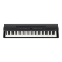
Do you have a question about the Yamaha P-85 and is the answer not in the manual?

Yamaha P-85 Specifications

General IconGeneral
TypeDigital Piano
Keys88
Voices10
Speakers2 x 6W
Polyphony64
EffectsReverb
Weight11.6 kg
ConnectivityHeadphone jack, Sustain pedal input
Demo Songs50
Included AccessoriesMusic Rest
Touch SensitivityHard, Medium, Soft, Fixed

Summary

SPECIFICATIONS

PANEL LAYOUT

CIRCUIT BOARD LAYOUT

DISASSEMBLY PROCEDURE

Lower Case Assembly

Procedure to remove the lower case assembly and FFC cover.

DM Circuit Board

Steps to remove the DM circuit board after the lower case.

Keyboard Assembly

Steps to remove the main keyboard assembly from the unit.

Disassembling the Keyboard Assembly

Detailed steps for taking apart the keyboard assembly's components.

Assembling the Keyboard Assembly

Instructions for reassembling the keyboard assembly, including hammers.

LSI PIN DESCRIPTION

μPD789022GB-A15-8E (XZ560100) CPU (MKS)

Description of pins for the μPD789022GB-A15-8E CPU.

AK4385ET (X6040A00) DAC (Digital to Analog Converter)

Description of pins for the AK4385ET DAC.

IC BLOCK DIAGRAM

CIRCUIT BOARDS

DM Circuit Board

Component layout diagram for the DM circuit board.

AM Circuit Board

Component layout diagram for the AM circuit board.

JK Circuit Board

Component layout diagram for the JK circuit board.

PN1 Circuit Board

Component layout diagram for the PN1 circuit board.

GHL88L Circuit Board

Component layout diagram for the GHL88L circuit board.

GHL88M Circuit Board

Component layout diagram for the GHL88M circuit board.

GHL88H Circuit Board

Component layout diagram for the GHL88H circuit board.

TEST PROGRAM

Preparation

List of required equipment and initial setup for the test program.

To enter Test Program

Procedure to turn on the power with specific keys pressed to enter the test mode.

Table 1 Test items

Detailed list of test items, keys, and judgment criteria for testing.

DATA BACKUP

BACKUP PROCEDURE

Step-by-step instructions for backing up data from the instrument to a PC.

MIDI IMPLEMENTATION CHART

MIDI DATA FORMAT

PARTS LIST

OVERALL ASSEMBLY

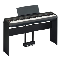
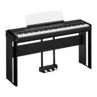
Exploded diagram showing the assembly of the entire piano unit.

KEYBOARD ASSEMBLY (GHL 鍵盤束線付 E)

Exploded diagram illustrating the assembly of the GHL keyboard mechanism.

FOOT PEDAL (フットペダル)

Exploded diagram showing the parts and assembly of the foot pedal unit.

ELECTRICAL PARTS (電気部品)

Detailed list of all electrical components used in the instrument.

L-85/L-85S KEYBOARD STAND (L-85/L-85S キーボードスタンド)

LP-5 PEDAL UNIT (LP-5 ペダルユニット)

PEDAL ASSEMBLY (ペダル Ass'y)

CIRCUIT DIAGRAM

BLOCK DIAGRAM & WIRING

Block diagram showing the overall system architecture and wiring connections between units.

DM CIRCUIT DIAGRAM

Detailed circuit diagram for the DM main board.

AM, HP, JK, PN1, PN2, PEDAL CIRCUIT DIAGRAM

Circuit diagrams for AM, HP, JK, PN1, PN2, and Pedal boards.

GHL88H, GHL88L, GHL88M CIRCUIT DIAGRAM (P-85/P-85S)

Circuit diagrams for the GHL88H, GHL88L, and GHL88M boards.

Related product manuals