Periodic maintenance and adjustment
89
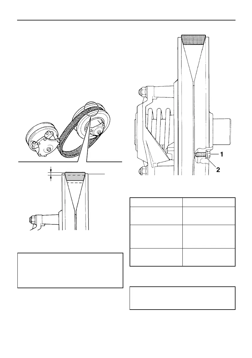
6. Remove the V-belt from the secondary
sheave assembly and primary sheave
assembly.
7. Temporarily install the new V-belt on the
secondary sheave assembly only, and
then measure the V-belt position. Do not
force the V-belt between the sheaves; the
secondary sliding and fixed sheaves
must touch each other.
8. If the V-belt position is incorrect, adjust it
by removing or adding a spacer on each
V-belt position adjusting bolt.
9. Tighten the V-belt position adjusting
bolts.
10. Install the V-belt over the primary sheave
assembly.
1. Edge of the secondary sheave assembly
2. Standard V-belt position
Standard V-belt position:
From 1.5 mm (0.06 in) above the
edge of the secondary sheave as-
sembly to 0.5 mm (0.02 in) below the
edge
1. V-belt position adjusting bolt
2. Spacer
V-belt position Adjustment
More than 1.5 mm
(0.06 in) above the
edge
Remove a spacer.
From 1.5 mm (0.06 in)
above the edge to 0.5
mm (0.02 in) below
the edge
Not necessary (it is
correct).
More than 0.5 mm
(0.02 in) below the
edge
Add a spacer.
V-belt position adjusting bolt tightening
torque:
10 Nm (1.0 m·kgf, 7.2 ft·lbf)
U8HV11E0.book Page 89 Monday, April 23, 2012 9:34 AM