39
Wiring Diagram
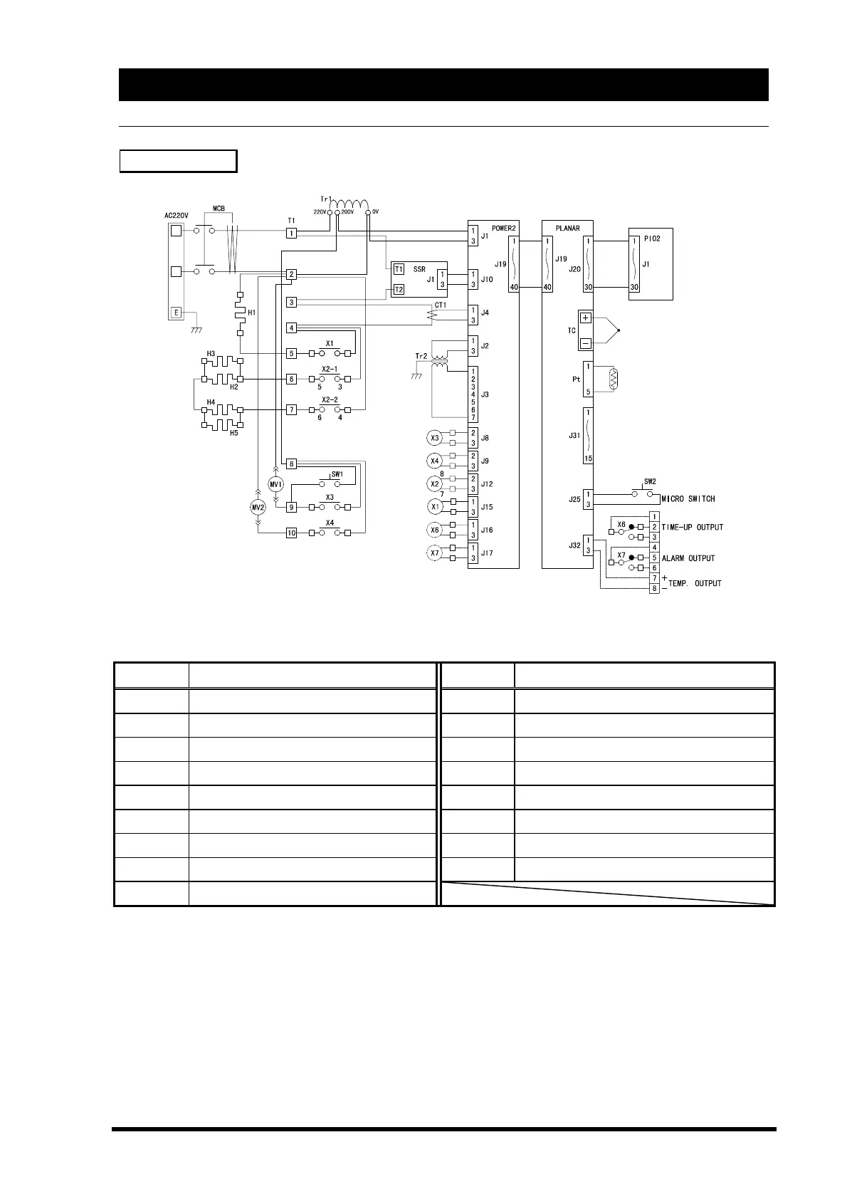
SM310/510
X1
◆Inside of dashed line is option
Symbol Name of Parts Symbol Name of Parts
Tr Transformer PIO2 Pio2 Board
X Relay POWER2 Power2 Board
CT Current Transformer SW1 Pressure Relief Switch
SSR Solid State Relay SW2 Micro Switch
MCB Circuit Breaker TC Sensor 2 (Thermocouple)
T Terminal PT Sensor 1 (Pt100 resistance thermometer)
MV1 Solenoid Exhaust Valve H1 Heater 1 (Sterilization)
MV2 Solenoid Drain Valve
H2〜4
Heater 2 (Drying)
PLANAR Planar Board