Chapter 9 Electrical System
4. Altemator
4LHA Seri,
2) To replace the IC regulator, disconnect the soldered
joint
of the IC regulator and pull out the two bolts. Do
not remove these two bolts except when replacing the
IC regulator.
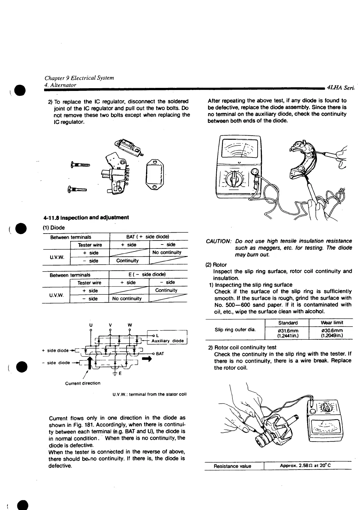
After repeating the above test, if any diode is found to
be
defective, replace the diode
assembly.
Since
there is
no terminal on the auxiliary diode, check the continuity
between both ends of the diode.
4-11.8
Inspection
and
adjustment
(1) Diode
Between
terminals
BAT
(+ side diode)
Tester
wire + side
- side
u.v.w.
+ side
No
continuity
u.v.w.
- side
Continuity
—^
Between
terminals
E(-
side diode)
Tester
wire
+ side
- side
U.V.W.
+ side
- side
No
continuity
t^oniinuiiy
w
o
-o L
+ side diode-
MM
-j-
Auxiliary diode
-
side
diode
/
Current direction
Jr
E
\J_P
o
BAT
U.V.W.:
terminal from the stator coil
Current flows only in one direction in the diode as
shown in Fig. 181. Accordingly, when there is continui-
ty between each terminal (e.g. BAT and U), the diode is
in normal condition. When there is no continuity, the
diode is defective.
When
the tester is connécted in the reverse of above,
there should be.no continuity. If there is, the diode is
defective.
CAUTION: Do not use high tensile insulation resistance
such as meggers, etc. for testing. The diode
may bum out.
(2) Rotor
Inspect the slip ring surface, rotor coil continuity and
insulation.
1) Inspecting the slip ring surface
Check
if the surface of the slip ring is sufficiently
smooth.
If the surface is rough, grind the surface
with
No.
500—600 sand paper. If it is contaminated
with
oil,
etc., wipe the surface clean
with
alcohol.
Slip
ring outer dia.
Standard
031.6mm
(15441
in.)
Wear
limit
030.6mm
(12049in.)
2) Rotor coil continuity test
Check
the continuity in the slip ring
with
the tester. If
there is no continuity, there is a wire break.
Replace
the rotor
coil.
Resistance
value
Approx.
2.58 Hat 20° C

 Loading...