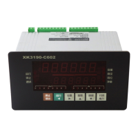
X K 3 1 9 0-C 602
Figure 3-8 Switch input and Output Interfaces
Attention: among the input and output terminals, it is prohibited to short 0V terminal
and +12V terminal. Or else, severe damage will be done to the indicator.
IX. Analog output
C602 indicator can choose from three Analog output modes: 0 ~ 5V, 0 ~ 10V voltage signal
output and 4 ~ 20mA current signal output. The current loop is provided by internal power
supply and the current signal can be adjusted to 0 ~ 20mA. The selection of output mode can be
done in the jumper JP1 ~ JP3 in power panel, see figure 3-9 for details. In the figure, the jumper
position is in conformity with these in power panel and X stands for the position of short circuit
ring. The factory setting of current loop is 4-20mA. The output value can be gross weight or net
weight by setting 【SET 1】 parameter 1F. The analog output switch is controlled by 【SET 1】
parameter 1E.
Jumper selection
Analog output
JP3 JP2 JP1
X 4—20mA
(factory setting)
X X
X
0—5V
X X
X X
0—10V
X
Definition of
catch-
weigher
terminal
S
t
a
n
d
b
y
S
t
a
n
d
b
y
C
h
a
n
n
el
5
C
h
a
n
n
e
l
4
C
h
a
n
n
el
3
C
h
a
n
n
e
l
2
C
h
a
n
n
el
1
O
p
e
r
a
ti
o
n
S
ta
n
d
b
y
S
t
a
n
d
b
y
S
ta
n
d
b
y
S
t
a
n
d
b
y
E
x
te
r
n
al
c
o
n
tr
o
l
S
t
o
p
Oper
ation
Standby
Corresponding
indicating
lamp on panel
O7 O6 O5 O4 O3 O2 O1 O0 I7 I6 I5 I4 I3 I2 I1 I0
 Loading...