2 Spindle Orientation
24 YASKAWA TM.A1000SW.063 Spindle Orientation A1000 Custom Software Supplement
To prevent unintended operation, the motor ratio that is selected when an orient digital input is applied latches until the
orient digital input is removed. If the state of the digital inputs 86h and 87h change during orientation, the new motor ratio
is effective after all orient digital inputs are removed.
Note: This software does not fully support multiple motor selection using the multi-function digital input function Motor 2 Select (H1-
= 16). However, the software can be utilized for winding change applications by setting PG Option Card Port for Motor 2
Selection parameter F1-30 = 0 and Orientation Encoder Card Selection parameter P1-10 = 0. When using two PG-X3 cards, it is
possible to run 2 different motors, provided that they share the same orientation encoder (the orientation encoder is always
defined by P1-10 regardless of Motor 1/2 selection).
Configuration 3: Indirect Drive with Proximity Sensor
When the motor and the spindle are connected through a drive train and the spindle does not have its own encoder, a
proximity sensor may be used. The proximity sensor configuration is enabled by setting Proximity Sensor Enable
parameter P1-13 = 1. The proximity sensor is connected as an external marker pulse as described in Encoder (PG) Option
Card Configuration and Wiring on page 29. Parameter P1-15 (Proximity Sensor Pulse State) allows for configuration of
both normally open and normally closed external marker pulses.
In this configuration (P1-13 = 1), the gear ratio of the drive train must be expressed as an exact number of motor
revolutions per revolution of the spindle. This gear ratio may be changed by modifying parameters P2-06, P2-07, and P2-
08, and then selecting the gear ratio using Gear Ratio Select digital inputs 86h and 87h as discussed in Configuration 2:
Indirect Drive with Orientation Encoder on page 23.
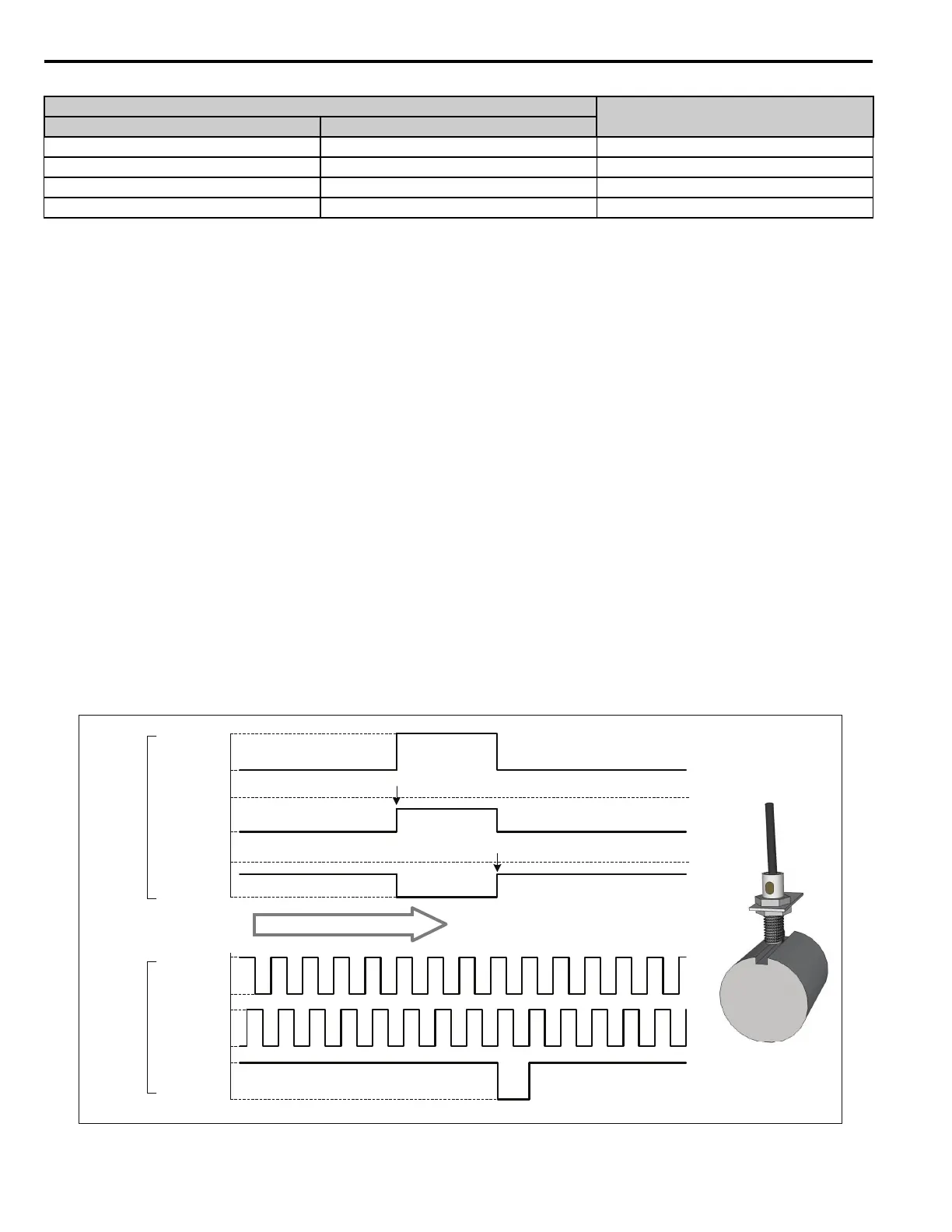
Proximity sensors measure the presence or absence of a target, and therefore the pulse width is often much larger than an
encoder Z channel, as indicated in Figure 9. Since the PG-X3 option card interprets the marker pulse as the rising edge of
the signal on the Z channel, the width of the marker pulse has a significant effect on the positioning accuracy in
applications which require orientation from forward and reverse operation.
Figure 9
Figure 9 Comparison of Encoder and Proximity Sensor Marker Pulses
Multi-Function Digital Input (H1-) Selection
Effective Parameter
87: Motor Ratio Selection 2 86: Motor Ratio Selection 1
Open Open P2-06: Motor Gear Ratio 1
Open Closed P2-07: Motor Gear Ratio 2
Closed Open P2-08: Motor Gear Ratio 3
Closed Closed P2-06: Motor Gear Ratio 1
A
Channel
B
Channel
Z
Channel
Typical
Encoder
P1-13 = 0
+V
0V
+V
0V
+V
0V
PNP N.C.
Prox
P1-16 = 1
PNP N.O.
Prox
P1-16 = 0
Proximity
Sensor
P1-13 = 1
Presence
of Object
Yes
No
+V
0V
+V
0V
PNP N.O.
Proximity Sensor
Rising Edge
Rising Edge
Forward Rotation

 Loading...


