2 Spindle Orientation
YASKAWA TM.A1000SW.063 Spindle Orientation A1000 Custom Software Supplement 29
Important Notes Regarding the Orient Window Functionality:
• If the P1-05 orient detection set window is set greater than the P1-06 reset window, the software limits P1-05 to the P1-
06 setting. This is required for the Orient Complete digital output function to work properly.
• The Orient Complete digital output is only active during orient when the commanded frequency reference is below the
P1-02 Creep Speed.
• The P1-07 ORT Set Time does not apply to the Orient Reset Window. If the actual position deviates from the
orientation position by more than P1-06 counts, the Orient Complete digital output opens. The P1-07 timer is reset and
the same ORT Set Time applies every time the spindle re-enters the Orient Set Window.
• If the drive is not running when an orient digital input is removed and reapplied while the drive is within the P1-06
window, the drive resumes position control within the orientation reset window so long as the commanded position
offset is not changed.
Encoder (PG) Option Card Configuration and Wiring
The PG-X3 or PG-B3 Installation Manual should be used to determine the Encoder (PG) Feedback card(s) needed. All
encoders must have quadrature feedback (A and B channels with compliments). The orientation encoder must also have a
marker pulse (referred to as the Z or C pulse). If not, an external sensor must be used to locate the marker position.
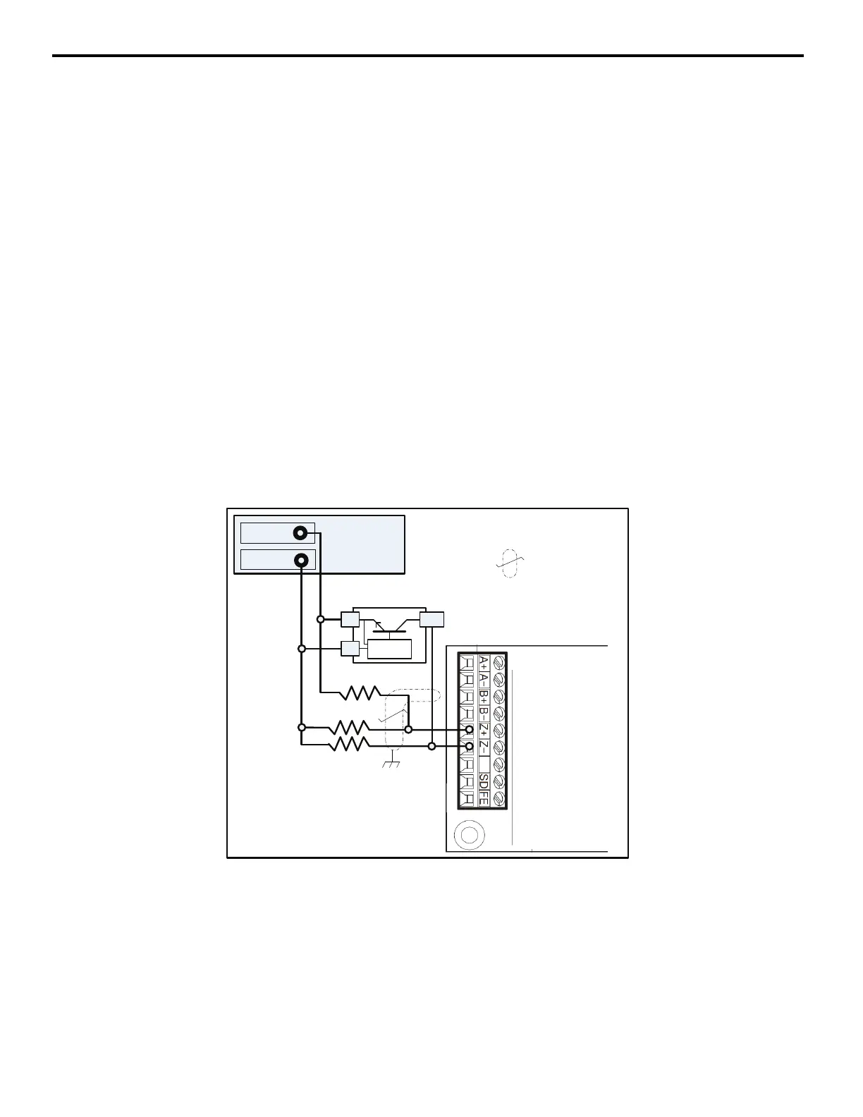
The PG-X3 Encoder Feedback card requires a line driver type circuit for the marker (Z/C pulse) input. Figure 13 shows
an example of how a +12 Vdc current sinking (open collector NPN) switch can be used to trigger the marker pulse input
of the encoder feedback card in situations where the application encoder does not have a Z/C channel. An external power
supply may be required. For best noise immunity, locate the resistor network at the sensor, not at the encoder feedback
card. Please note that the sensor must be able to handle at least 22 mA of current draw. For exact application wiring,
consult Yaskawa Application Engineering with the exact sensor specifications.
Figure 13
Figure 13 External Marker Pulse Wiring Diagram: NPN
PG-X3Encoder
FeedbackCard
12VDC+/- 5%
PowerSupply
+12VDC
Common
R3
R1
R2
NPNExternal
Marker
Allresistors560 Ω,
tolerance10%,½Watt
Shielded
TwistedPair
-
+
OC

 Loading...


