2 Spindle Orientation
30 YASKAWA TM.A1000SW.063 Spindle Orientation A1000 Custom Software Supplement
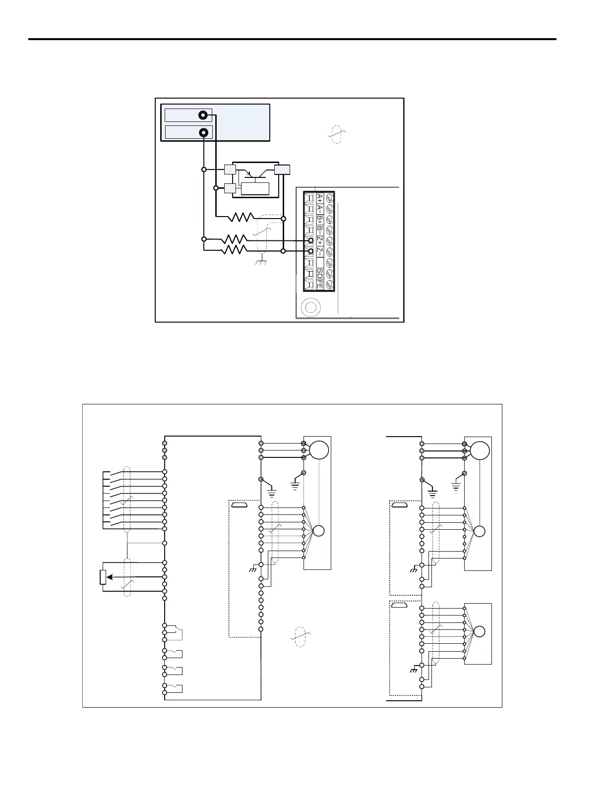
Figure 14 is an example of how a +12 Vdc current sourcing (open collector PNP) switch can be used to trigger the
marker pulse input.
Figure 14
Figure 14 External Marker Pulse Wiring Diagram: PNP
Drive Wiring Examples
The examples in Figure 15 are typical wiring diagrams for the direct and indirect positioning methods discussed in
Application Configurations on page 23.
Figure 15
Figure 15 Wiring of Drive for Application Examples
PG-X3Encoder
FeedbackCard
12VDC+/- 5%
PowerSupply
+12VDC
Common
R3
R1
R2
PNPExternalMarker
Allresistors560 Ω,
tolerance10%,½Watt
Shielded
TwistedPair
OC
-
+
IM
GND
PG-X3OptionCard
PG
U/T1
V/T2
W/T3
A1000
R/L1
S/L2
T/L3
S1
S2
S3
S4
S5
S6
S7
S8
E(G)
A1Input(0to+/- 10VDC)
A2Input
+VSupply(+10.5VDC)
A3Input
ACCommon
1BT2BT
Motor
Example1:ClosedLoopVector
Control‒DirectDrive
IP
IG
a+
a-
b+
b-
M3
M4
MA
MB
MC
-VSupply(-10.5VDC)
SpeedReference
H2-0X=41h:
HomePosition
H2-0X=40h:
OrientComplete
Position
Encoder
Note:Anexternalpowersupplymaybe
required.ThePG-X3hasa200mA
powersupply.Checktheratedcurrentof
bothencoders.
Example2:ClosedLoopVector
ControlwithPositionEncoder
M1
M2
M5
M6
Fault
z+
z-
A+
A-
B+
B-
Z+
Z-
SD
FE
PGPower
PGGND
ForwardRun
ReverseRun
OrientCMD
OffsetSel1
SN
2kΩ
ShieldedTwisted
Pair
IM
GND
PG-X3OptionCard1
PG
U/T1
V/T2
W/T3
TB2 TB1
Motor
IP
IG
A+
A-
B+
B-
Z+
Z-
SD
FE
PGPower
PGGND
PG-X3OptionCard2
PG
TB2 TB1
IP
IG
A+
A-
B+
B-
Z+
Z-
SD
FE
PGPower
PGGND
Motor
Encoder
CN5-C
CN5-C
CN5-B
(H1-01=40h)
(H1-02=41h)
(H1-03=80h)
(H1-04=84h)

 Loading...


