2 Spindle Orientation
28 YASKAWA TM.A1000SW.063 Spindle Orientation A1000 Custom Software Supplement
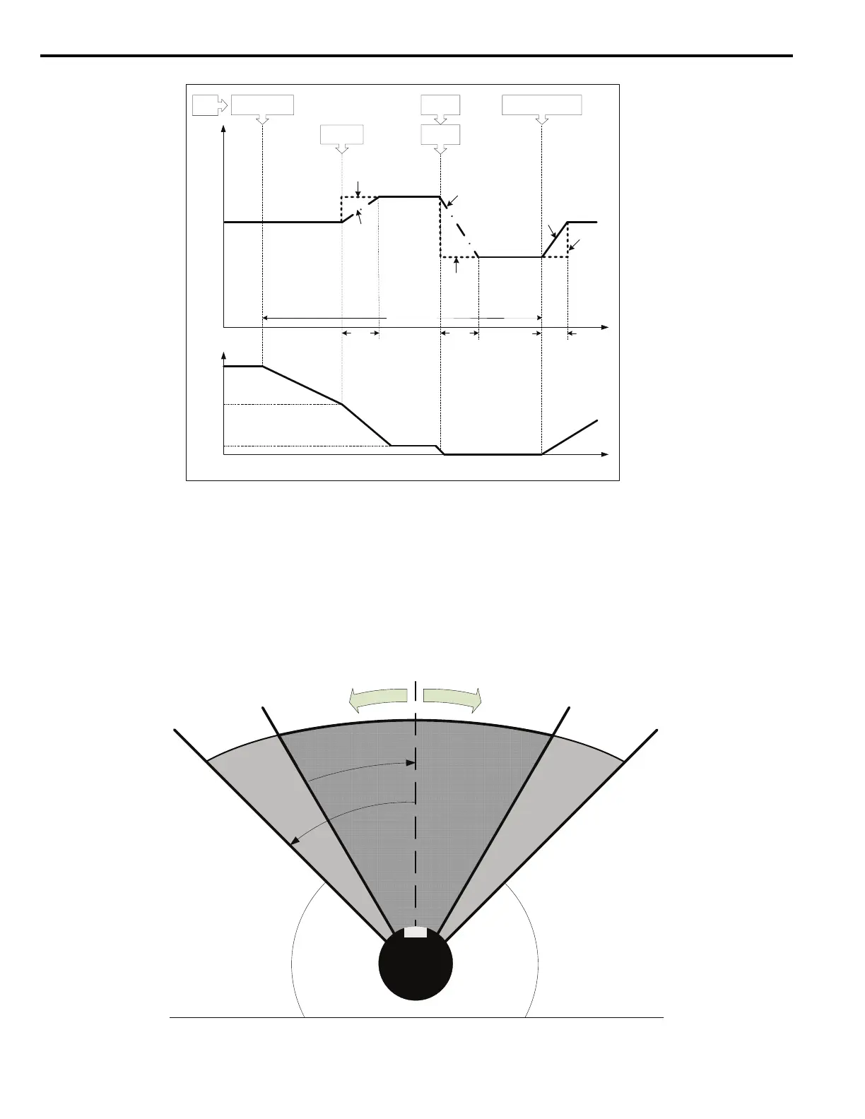
Figure 11
Figure 11 ASR Gain/Time Change During Orient
Orientation Set/Reset Window
Figure 12 visualizes the Orientation windows P1-05 and P1-06. The motor enters the dark grey Orient Set Window once
the difference between the current position and the desired Marker Offset is less than P1-05 counts. If the current position
is maintained within the dark grey window for longer than the Orientation Set Time P1-07, the multi-function digital
output H2- set to 40h will go high. This output remains high as long as the shaft maintains its position within
+/- P1-06 counts of the Marker Offset, which is the light grey Orientation Reset Window in Figure 12.
Figure 12
Figure 12 Orientation Set and Reset Windows
*P=C5-01
*I=C5-02
0
ASR
PGain,
ITime
P=P2-10
I=P2-11
Time[s]P2-11
P
I
DuringOrient
P2-13
P
I
P=P2-12
I=P2-13
Orient
Complete
Acceleration,
OrientCMDRemoved
Deceleration,
80hOrientCMD
Event
*AssumesC5-07=0.0Hz,speed-dependentASRvaluesdisabled.
FreqRef=
P1-01
Zero
Servo
P
Motor
Speed
[Hz]
(U1-05)
Time[s]
0
P1-01
P1-02
I
C5-02
MotorShaft
OrientPosition
OrientSet
Window
Orient
Reset
Window
S
e
t
i
f
<
P
1
-
0
5
c
o
u
n
t
s
R
e
s
e
t
i
f
>
P
1
-
0
6
c
o
u
n
t
s

 Loading...


