Terminal Block Configuration
2-5
Terminal Block Configuration
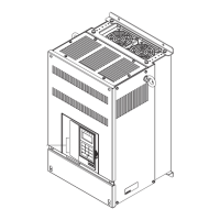
The following figures show the terminal arrangements for MxC. Refer to Fig. 2.3 for 5.5 kW and 11 kW
MxCs, Fig. 2.4 for a 22 kW MxC, and Fig.2.5 for 45 kW and 75 kW MxCs.
Fig 2.3 Terminal Arrangement (Model: CIMR-ACA4011)
Fig 2.4 Terminal Arrangement (Model: CIMR-ACA4022)
Fig 2.5 Terminal Arrangement (Model: CIMR-ACA2045)
Main circuit terminals
Control circuit terminals
Charge indicator
Ground terminal
T
U
V
R
P
4. 5. 6.
76 86
96
Control circuit terminals
Main circuit terminals
Ground terminal
Charge indicator
Control circuit terminals
Main circuit terminals
Ground terminal
Charge indicator
 Loading...