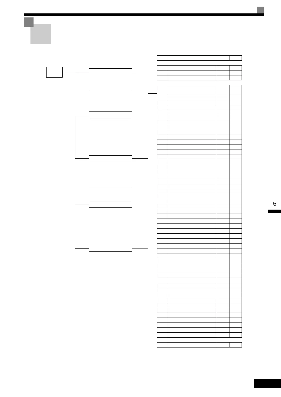
MENU
Drive Mode
MxC can be begin to run the
application, and the operation
status can be viewed.
Quick Programming Mode
Quick setting mode:
Sets or monitors the parame-
ters of QUICK-START (Q).
Advanced Programming Mode
Program Mode:
Sets or monitors the parame-
ters. The items that can be
monitored depend on the set-
ting of the access level.
Verify Mode
Parameters changed from the
default settings can be moni-
tored or set.
Auto-Tuning Mode
Auto-Tuning:
If the line-to-line resistance for
vector control or V/f Control
Method is measured, automat-
ically sets motor parameters
by inputting Auto-Tuning data
(from motor nameplate).
No. Function Display Page
U1 Status Monitor Parameters Monitor 5-57
U2 Fault Trace
Fault Trace
5-62
U3 Fault History
Fault History
5-63
A1 Initialize Mode
Initialization
5-7
A2 User-Specified Setting Mode
User
Parameter
5-8
b1 Operation Mode Selections
Sequence
5-9
b2 DC Injection Braking
DC Braking
5-10
b3 Speed Search
Speed
Search
5-11
b4 Timer Function
Delay Timers
5-12
b5 PID Control
PID Control
5-12
b6 Dwell Functions
Reference
Hold
5-14
b7 Droop Control
Droop
Control
5-14
b9 Zero-Servo
Zero Servo
5-15
C1 Acceleration/Deceleration
Accel/Decel
5-16
C2 S-Curve Acceleration/Deceleration
S-Curve
Acc/Dcc
5-17
C3 Motor Slip Compensation
Motor-Slip
Comp
5-17
C4 Torque Compensation
To rq ue
Comp
5-18
C5 Speed Control (ASR)
ASR Tuning
5-19
C6 Carrier Frequency
Carrier Freq
5-19
d1 Preset Reference
Preset
Reference
5-20
d2 Reference Limits
Reference
Limits
5-21
d3 Jump Frequencies
Jump
Frequencies
5-22
d4 Reference Frequency Hold
Sequence
5-22
d5 Torque Control
Torque Control
5-23
d6 Field Weakening
Field-
weakening
5-24
E1 V/f Pattern
V/f Pattern
5-25
E2 Motor Setup
Motor
Setup
5-26
E3 Motor 2 V/f Pattern
V/f Pattern 2
5-27
E4 Motor 2 Setup
Motor Setup
2
5-27
F1 PG Option Setup
PG Option
Setup
5-29
F2 Analog Reference Card
AI-14 Setup
5-30
F3 Digital Reference Card
DI-08, 16
Setup
5-31
F4 Analog Monitor Cards
AO-08, 12
Setup
5-31
F5 Digital Output Cards
DO-02,08
Setup
5-32
F6 Communications Option Cards
ComOPT
Setup
5-33
H1 Multi-Function Digital Inputs
Digital
Inputs
5-34
H2 Multi-Function Digital Outputs
Digital
Outputs
5-37
H3 Analog Inputs
Analog
Inputs
5-39
H4 Multi-Function Analog Outputs
Analog
Outputs
5-41
H5 MEMOBUS Communications
Serial Com
Setup
5-42
L1 Motor Overload
Motor
Overload
5-43
L2 Power Loss Ridethrough
PwrLoss
Ridethru
5-44
L3 Stall Prevention
Stall
Prevention
5-45
L4 Reference Detection
Ref
Detection
5-46
L5 Fault Restart
Fault Restart
5-47
L6 Torque Detection
To rq ue
Detection
5-47
L7 Torque Limits
Torque Limit
5-48
L8 Hardware Protection
Hdwe
Protection
5-49
n1 Hunting Prevention Function
Hunting Prev
5-50
n2
Speed Feedback Protection Control
AFR 5-51
n5 Feed Forward
Feedfoward
Cont
5-51
o1 Monitor Select
Monitor
Select
5-52
o2 Multi-Function Selections
Key
Selections
5-53
o3 Copy Function
COPY
Function
5-54
T1 Motor Auto-Tuning
Auto-Tuning
5-55
 Loading...