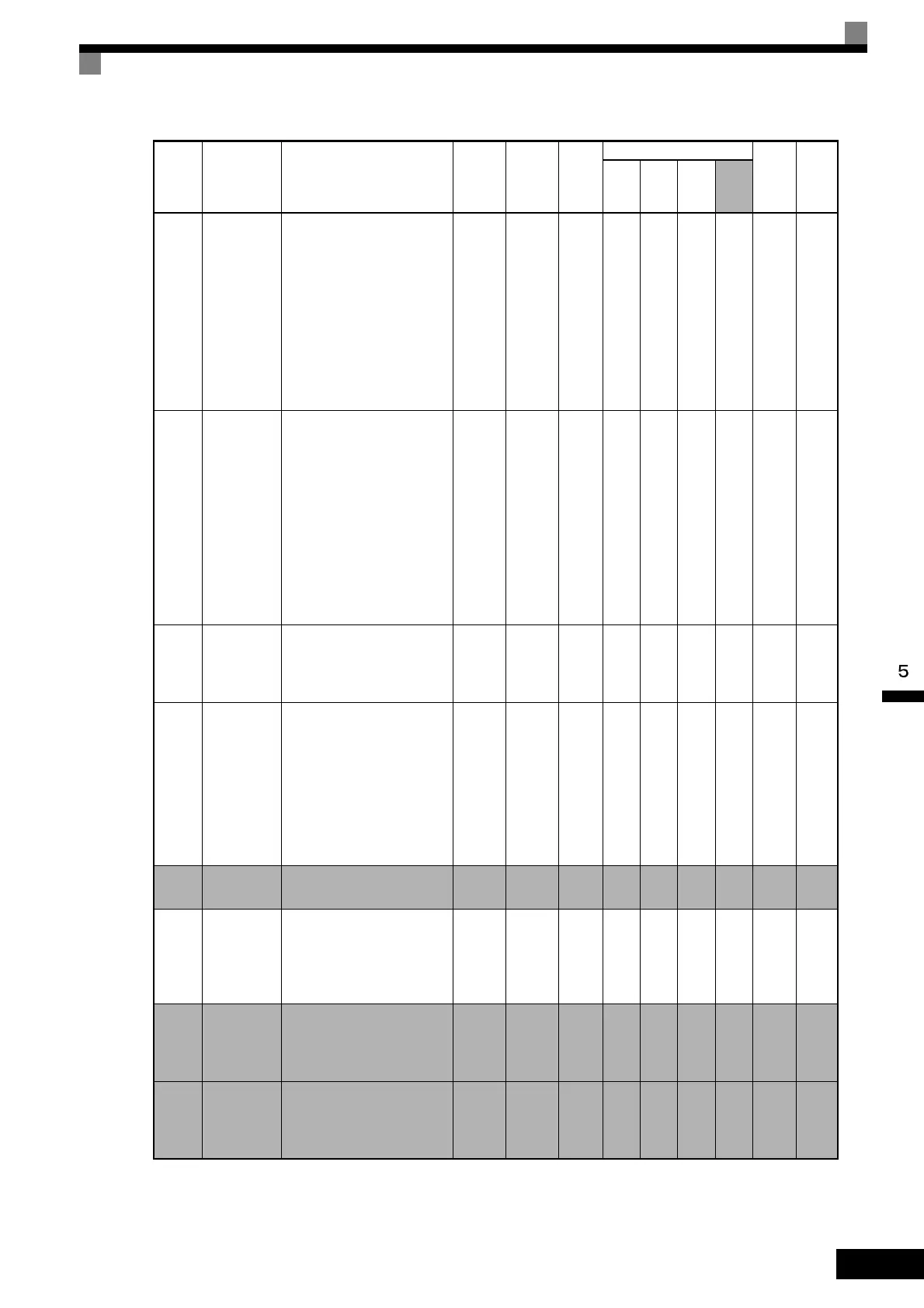
User Constant Tables
5-71
* 1. The factory setting depends on the Inverter capacity. The value for a 200 V Class Inverter of 0.4 kW is given.
* 2. Applicable for F7-series Inverters with software versions PRG: 1033 or later.
o2-05
Frequency
reference
setting
method
selection
When the frequency refer-
ence is set on the Digital
Operator frequency refer-
ence monitor, sets whether
the Enter Key is necessary.
0: Enter Key needed
1: Enter Key not needed
When set to 1, the Inverter
accepts the frequency refer-
ence without Enter Key
operation.
0 or 1 0 No A A A A 509H 6-149
o2-06
Operation
selection
when digi-
tal operator
is discon-
nected
Sets the operation when the
Digital Operator is discon-
nected.
0: Disabled (Operation
continues even if the
Digital Operator is
disconnected.)
1: Enabled (OPR is detected
at Digital Operator
disconnection. Inverter
output is cut off, and fault
contact is operated.)
0 or 1 0 No A A A A 50AH -
o2-07
Cumulative
operation
time setting
Sets the cumulative opera-
tion time in hour units.
Operation time is calculated
from the set values.
0 to
65535
0 hr No A A A A 50BH 6-149
o2-08
Cumulative
operation
time selec-
tion
0: Cumulative time when
the Inverter power is on.
(All time while the
Inverter power is on is
accumulated.)
1: Cumulative Inverter run
time. (Only Inverter
output time is
accumulated.)
0 or 1 0 No A A A A 50CH -
o2-09
*2
For factory
adjustment
For adjustment at factory
Do not set this constant.
0, 3 0 No A A A A 50DH -
o2-10
Fan opera-
tion time
setting
Set the initial value of the
fan operation time using
time units.
The operation time accumu-
lates from the set value.
0 to
65535
0 hr No A A A A 50EH 6-149
o2-12
Fault trace/
fault his-
tory clear
function
0: Disabled (U2 and U3
constants are on hold.)
1: Enabled (Initializes U2
and U3 constants.)
0 or 1 0 No A A A A 510H -
o2-14
Output
power mon-
itor clear
selection
0: Holds output power mon-
itor.
1: Initializes output power
monitor. (Returns to 0.)
0 or 1 0 No A A A A 512H 5-77
Con-
stant
Number
Name Description
Setting
Range
Factory
Setting
Change
during
Opera-
tion
Control Methods
MEMO
BUS
Regis-
ter
Page
V/f
V/f
with
PG
Open
Loop
Vec-
tor
Flux
Vec-
tor

 Loading...