4 OPERATION
45
Constant
No.
CheckedRemarksSet Value
(On Nameplate)
Name
E1-11 Motor q-axis inductance (Lq)
E1-13 Induced voltage (Ke)
C2-12 Leading phase compensation
amount
(∆θ)
E1-14 Variable torque/constant torque
selection
See remarks. If the motor model starts with SSR, E1-14 = 0.
If the motor model starts with SST, E1-14 = 1.
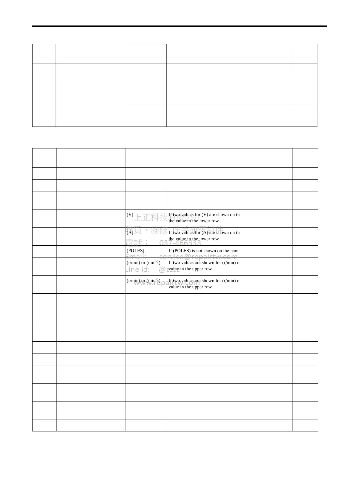
Table 12 Motor Constants Setup for Flux Vector Control
Constant
No.
Name Set Value
(On Nameplate)
Remarks Checked
A1-01 Constant access level 4
A1-02 Control method selection 6 6: Flux vector control
E1-02 Motor capacity selection See remarks. Refer to Table A-6 Motor Capacity Selection List in Appendix
4.
E1-03 Motor rated voltage (V) If two values for (V) are shown on the nameplate, set E1-03 to
the value in the lower row.
E1-04 Motor rated current (A) If two values for (A) are shown on the nameplate, set E1-04 to
the value in the lower row.
E1-05 Number of motor poles (POLES) If (POLES) is not shown on the nameplate, set E1-05 to 6.
E1-06 Motor max. speed (r/min) or (min
-1
) If two values are shown for (r/min) or (min
-1
), set E1-06 to the
value in the upper row.
E1-07 Motor base speed (r/min) or (min
-1
) If two values are shown for (r/min) or (min
-1
), set E1-07 to the
value in the upper row.
E1-08 Motor min. speed Any value
between 0 and
the base speed
Initial setting: 30 min
-1
E1-09 Motor armature resistance (R1)
E1-10 Motor d-axis inductance (Ld)
E1-11 Motor q-axis inductance (Lq)
E1-13 Induced voltage (Ke)
C2-13 PG zero-pulse compensation
amount
(∆θ) If the PG zero-pulse is adjusted, the set value of C2-13 changes.
E1-14 Variable torque/constant torque
selection
1
Motor speed detection check
Check if the motor speed is detected correctly as explained in
4.3 (3) (d).
PG zero-pulse adjustment
Adjust the PG zero-pulse as explained in 4.3 (3) (e).
 Loading...