78
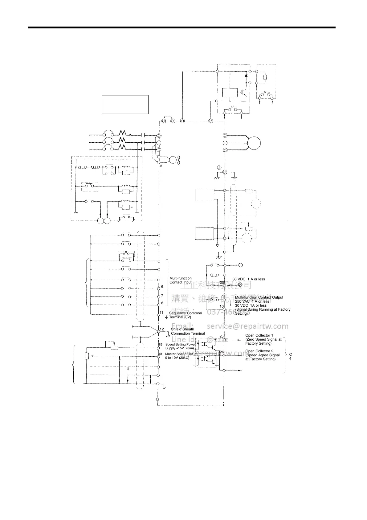
For models CIMR-SSA2018, -SSA2022 (200 V Class 18.5, 22 kW)
(ℓ 2)
3-Phase
Power Supply
200 to 230 V
50/60 Hz
R
S
T
M
r(ℓ
1
)
Cooling Fan
(12)
Short-circuit Bar
(Provided as
Standard)
Ground (100Ω or less)
Braking Unit
(Option)
P
B
Braking Resistor
Unit (Option):
1
2
Overload Relay Trip Contact
Level
Detection
34
U
V
W
Motor
M
¨ 1
MCCB
R
MC
S
T
¨ 2
©
¨ 3
Braking Unit
34
THRX OFF
ON
MC
SA
Overload Relay Trip Contact
of Braking Resistor Unit
1
2
MC
TRX
TRX
20 18
Fault
Contact
SA
SA
THRX
MC
Forward Run/Stop
Reverse Run/Stop
Factory
Setting
External Fault
Fault Reset
Multi-step Speed Setting 1
(Master/Aux Change)
Multi-step Speed
Setting 2
Jog Reference
External Baseblock
2kΩ
2kΩ
0 to +10 V
4to20mA
P
0 to +10 V
P
0V
P
17 (Aux Speed Ref. at
Factory Setting)
15 Speed Setting Power
Supply +15V 20mA
3
4
5
6
7
8
Analog
Monitor 1
11
0V
1 Forward Run when
CLOSED
2 Reverse Run when
CLOSED
Multi-function
Contact Input
Sequence Common
Terminal (0V)
12 Shield Sheath
Connection Terminal
13 Master Speed Ref.
0 to 10V (20kΩ)
14 Master Speed Ref.
4 to 20mA (250Ω)
16 Multi-function Analog Input
0 to 10V (20kΩ)
33 Speed Setting Power Supply
-15V 20mA
21
22
23
+
AM
+
−
Multi-function Analog Output
-10 to +10V 2mA
(Output Current at Factory
Setting)
SM
Multi-function Analog Output
−10 to +10 V 2mA
(Rotation Speed at Factory
Setting)
−
Multi-function Open
Collector Output
48 V 50 mA or less
Multi-function
Output Common
27
Open Collector 2
(Speed Agree Signal
at Factory Setting)
26
Open Collector 1
(Zero Speed Signal at
Factory Setting)
25
Multi-function Contact Output
250 VAC 1 A or less
30 VDC 1A or less
(Signal during Running at Factory
Setting)
10
9
20
19
Fault Contact Output
250 VAC 1 A or less
30 VDC 1 A or less
18
Analog
Monitor 2
: When using the braking resistor unit, set constant L3-01 to “0” (overvoltage prevention selection
disabled). If it is not changed, the inverter may not stop within set decel time.
Use sequencer to break
power supply side on
overload relay trip contact
of braking resistor unit.
VS-686SS5
¨¨
0
©
0
©
External
Speed
Reference
18
20
 Loading...