EasyManuals Logo

YASKAWA F7 User Manual

YASKAWA F7
255 pages
To Next Page IconTo Next Page
To Previous Page IconTo Previous Page
Page #17 background imageLoading...
Page #17 background image
Physical Installation 1 - 6
Models CIMR-F7U2022 thru 2110 and 4030 thru 4300
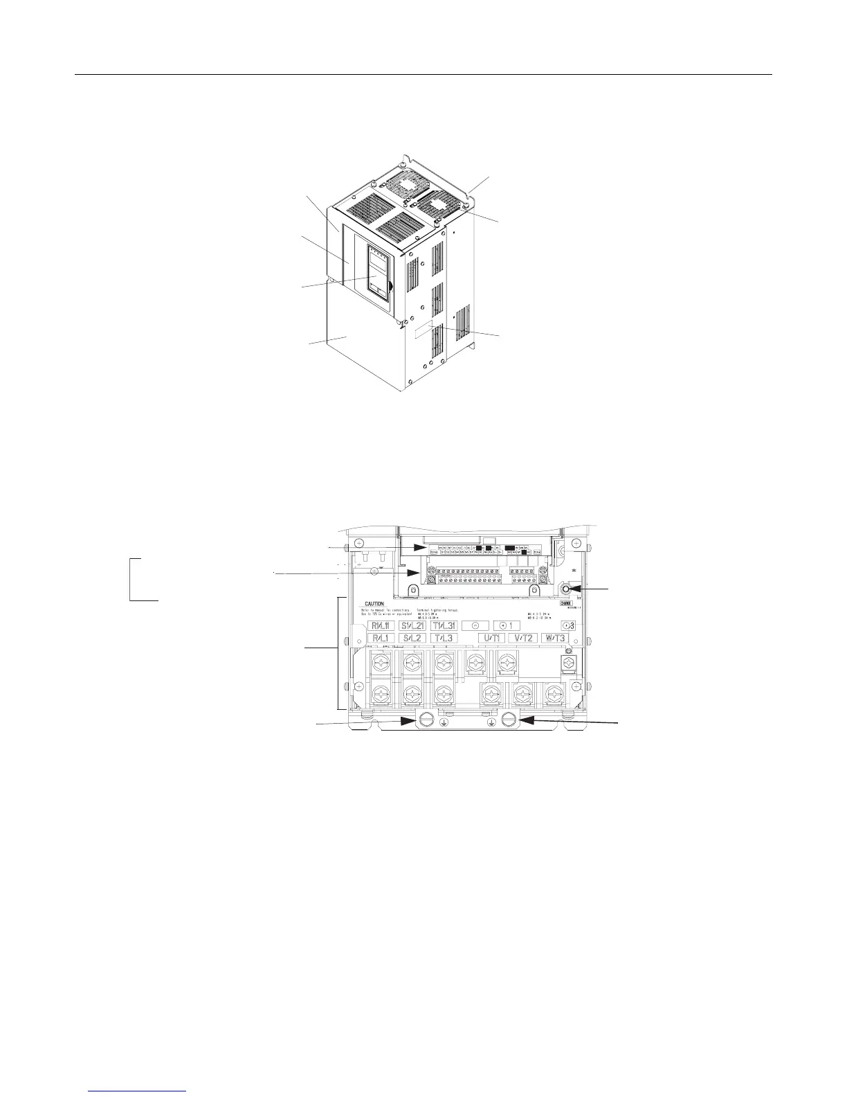
The external appearance, component names, and terminal arrangement of the Drive are shown in Fig 1.6 and 1.7.
Fig 1.6 Drive Appearance
Fig 1.7 Terminal Arrangement (Terminal Cover Removed)
Mounting holes
Cooling fan
Nameplate
Drive cover
Front cover
Digital Operator
Terminal cover
Mounting holes
Cooling fan
Nameplate
Drive cover
Front cover
Digital Operator
Terminal cover
Charge indicator
Main circuit
terminals
Ground terminal
Ground terminal
Control circuit terminal layout label
Control circuit terminals
See Fig. 2.3 for actual
terminal layout
{
http://www.aotewell.com
Aotewell
Email: Sales@aotewell.com
Tel: +(86) 755 8660 6182
Aotewell
http://www.aotewell.com

Table of Contents

Other manuals for YASKAWA F7

Questions and Answers:

Question and Answer IconNeed help?

Do you have a question about the YASKAWA F7 and is the answer not in the manual?

YASKAWA F7 Specifications

General IconGeneral
SeriesF7
TypeDC Drive
FeedbackTachometer, Encoder
CommunicationRS-485, DeviceNet, Profibus, Modbus
Protection FeaturesOvercurrent, Overvoltage, Undervoltage, Overheating, Short Circuit
Storage Temperature-20°C to +70°C (-4°F to 158°F)
Humidity95% RH or less (non-condensing)
Enclosure RatingIP20
Input Voltage200-240V AC, 380-480V AC

Related product manuals