Electrical Installation 2 - 22
DIP Switch S1 and Jumper CN15
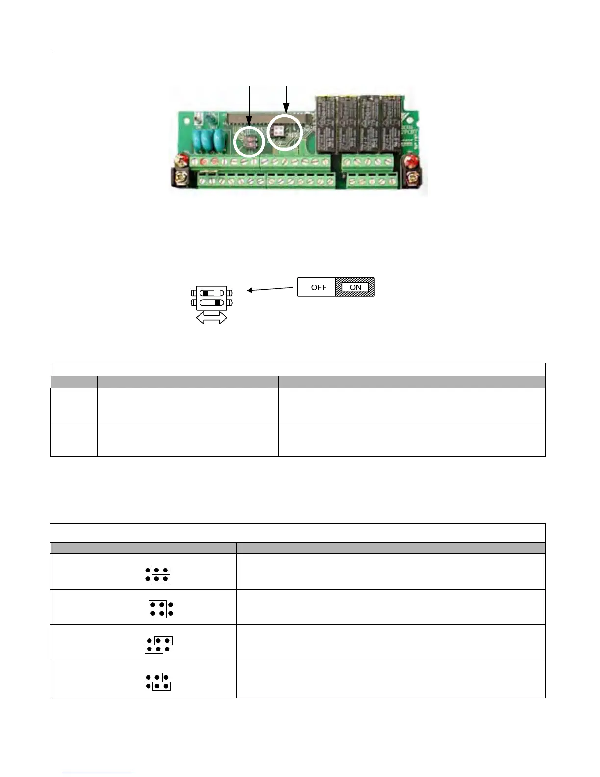
Fig 2.10 DIP Switch S1 and Jumper CN15 Location
Dip Switch S1
DIP Switch S1 is described in this section. The functions of DIP switch S1 are shown in Table 2.13.
Fig 2.11 DIP Switch S1 Function
Jumper CN15
Jumper CN15 is described in this section. The jumper position of CH1 and CH2 determines the signal level of the
multi-function analog output FM and AM, respectively. The functions and positions of CN15 are shown in Table 2.14.
Table 2.13 DIP Switch S1
Name Function Setting
S1-1 RS-485 and RS-422 terminating resistance
OFF: No terminating resistance
ON: Terminating resistance of 110Ω
Factory Default = OFF
S1-2 Input method for analog input A2
OFF: 0 to 10Vdc or -10 to 10Vdc (internal resistance: 20KΩ)
ON: 4-20mA (internal resistance: 250Ω)
Factory Default = ON
Table 2.14 Jumper CN15 Configuration Options
Jumper CN15 Configuration Analog Output Monitor Configuration
Voltage Output (0-10Vdc) for terminals FM-AC (CH1) and AM-AC (CH2)
Current Output (4-20mA) for terminals FM-AC (CH1) and AM-AC (CH2)
Voltage Output (0-10Vdc) for terminals FM-AC (CH1)
Current Output (4-20mA) for terminals AM-AC (CH2)
Current Output (4-20mA) for terminals FM-AC (CH1)
Voltage Output (0-10Vdc) for terminals AM-AC (CH2)
S1
S1
ON/OFF
position
DIP Switch S1 located on
terminal board.
2
1
CH1
CH2
CH1
CH2
CH1
CH2
CH1
CH2
CN15
Email: Sales@aotewell.com