Electrical Installation 2 - 3
Wiring Main Circuit Terminals
Applicable Wire Sizes and Closed-loop Connectors
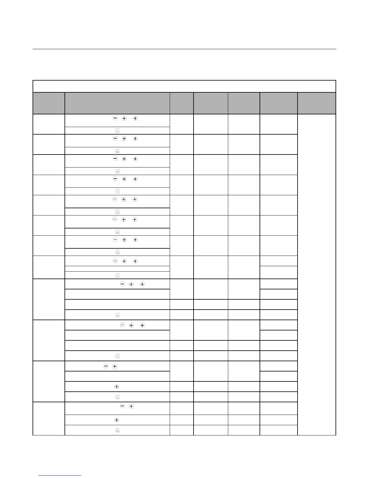
Select the appropriate wires and crimp terminals from Table 2.1 and Table 2.2. Refer to instruction manual TOE-C726-2 for
Braking Resistor Unit and Braking Unit wire sizes.
Table 2.1 208-240Vac Wire Sizes and Connector Specifications
Drive Model
CIMR-F7U
Terminal Symbol
Terminal
Screws
Clamping
Torq ue
lb. in.
(N•m)
Possible Wire
Sizes AWG
(mm
2
)
*1
Recommended
Wire Size AWG
(mm
2
)
*2
Wire
Type
20P4
R/L1, S/L2, T/L3, , 1, 2, B1, B2
U/T1, V/T2, W/T3
M4
10.6 to 13.2
(1.2 to 1.5)
14 to 10
(2 to 5.5)
14
(2)
600Vac
UL Approved
vinyl-sheathed
or equivalent
20P7
R/L1, S/L2, T/L3, , 1, 2, B1, B2
U/T1, V/T2, W/T3
M4
10.6 to 13.2
(1.2 to 1.5)
14 to 10
(2 to 5.5)
14
(2)
21P5
R/L1, S/L2, T/L3, , 1, 2, B1, B2
U/T1, V/T2, W/T3
M4
10.6 to 13.2
(1.2 to 1.5)
14 to 10
(2 to 5.5)
14
(2)
22P2
R/L1, S/L2, T/L3, , 1, 2, B1, B2
U/T1, V/T2, W/T3
M4
10.6 to 13.2
(1.2 to 1.5)
14 to 10
(2 to 5.5)
14
(2)
23P7
R/L1, S/L2, T/L3, , 1, 2, B1, B2
U/T1, V/T2, W/T3
M4
10.6 to 13.2
(1.2 to 1.5)
12 to 10
(3.5 to 5.5)
12
(3.5)
25P5
R/L1, S/L2, T/L3, , 1, 2, B1, B2
U/T1, V/T2, W/T3
M4
10.6 to 13.2
(1.2 to 1.5)
12 to 10
(3.5 to 5.5)
10
(5.5)
27P5
R/L1, S/L2, T/L3, , 1, 2, B1, B2
U/T1, V/T2, W/T3
M5
21.99
(2.5)
8 to 6
(8 to 14)
8
(8)
2011
R/L1, S/L2, T/L3, , 1, 2, B1, B2
M5
21.99
(2.5)
6 to 4
(14 to 22)
4
(22)
U/T1, V/T2, W/T3
6
(14)
2015
R/L1, S/L2, T/L3, , 1, 2
M6
35.2 to 43.99
(4.0 to 5.0)
4 to 2
(22 to 38)
3
(30)
U/T1, V/T2, W/T3
4
(22)
B1, B2 M5
21.99
(
2.5)
8 to 6
(8 to 14)
Application
Dependent
M6
35.2 to 43.99
(4.0 to 5.0)
4
(22)
4
(22)
2018
R/L1, S/L2, T/L3, , 1, 2
M8
79.2 to 87.97
(9.0 to 10.0)
3 to 2
(30 to 38)
2
(38)
U/T1, V/T2, W/T3
3
(30)
B1, B2 M5
21.99
(2.5)
8 to 6
(8 to 14)
Application
Dependent
M6
35.2 to 43.99
(4.0 to 5.0)
4
(22)
4
(22)
2022
R/L1, S/L2, T/L3, , 1, R1/L11, S1/L21, T1/L31
M8
79.2 to 87.97
(9.0 to 10.0)
N/A
1
(50)
U/T1, V/T2, W/T3,
2
(38)
3
M6
35.2 to 43.99
(4.0 to 5.0)
N/A
Application
Dependent
M8
79.2 to 87.97
(9.0 to 10.0)
N/A
4
(22)
2030
R/L1, S/L2, T/L3, , 1 U/T1,
V/T2, W/T3, R1/L11, S1/L21, T1/L31
M8
79.2 to 87.97
(9.0 to 10.0)
N/A
1/0
(60)
3
M6
35.2 to 43.99
(4.0 to 5.0)
N/A
Application
Dependent
M8
79.2 to 87.97
(9.0 to 10.0)
N/A
4
(22)
Email: Sales@aotewell.com