Electrical Installation 2 - 4
2037
R/L1, S/L2, T/L3, , 1 U/T1,
V/T2, W/T3, R1/L11, S1/L21, T1/L31
M10
154.8 to 197.9
(17.6 to 22.5)
N/A
4/0
(100)
600Vac
UL Approved
vinyl-sheathed
or equivalent
3
M8
77.4 to 95.0
(8.8 to 10.8)
N/A
Application
Dependent
M10
154.8 to 197.9
(17.6 to 22.5)
N/A
2
(38)
r/
l1, s/l2
M4
11.4 to 12.3
(1.3 to 1.4)
N/A
16
(1.25)
2045
R/L1, S/L2, T/L3, , 1, R1/L11, S1/L21, T1/L31
M10
154.8 to 197.9
(17.6 to 22.5)
N/A
300
(150)
U/T1, V/T2, W/T3
250
(125)
3
M8
77.4 to 95.0
(8.8 to 10.8)
N/A
Application
Dependent
M10
154.8 to 197.9
(17.6 to 22.5)
N/A
1
(50)
r/
l1, s/l2
M4
11.4 to 12.3
(1.3 to 1.4)
N/A
16
(1.25)
2055
R/L1, S/L2, T/L3, , 1, U/T1, V/T2, W/T3,
R1/L11, S1/L21, T1/L31
M10
154.8 to 197.9
(17.6 to 22.5)
N/A
1/0 X 2P
(60 X 2P)
3
M8
77.4 to 95.0
(8.8 to 10.8)
N/A
Application
Dependent
M10
154.8 to 197.9
(17.6 to 22.5)
N/A
1/0
(60)
r/
l1, s/l2
M4
11.4 to 12.3
(1.3 to 1.4)
N/A
16
(1.25)
2075
R/L1, S/L2, T/L3, R1/L11, S1/L21, T1/L31
M10
154.8 to 197.9
(17.6 to 22.5)
N/A
4/0 X 2P
(100 X 2P)
U/T1, V/T2, W/T3 N/A
3/0 X 2P
(80 X 2P)
, 1
M12
276.2 to 344.8
(31.4 to 39.2)
N/A
3/0 X 2P
(80 X 2P)
3
M8
77.4 to 95.0
(8.8 to 10.8)
N/A
Application
Dependent
M12
276.2 to 344.8
(31.4 to 39.2)
N/A
3/0
(80)
r/
l1, s/l2
M4
11.4 to 12.3
(1.3 to 1.4)
N/A
16
(1.25)
2090
R/L1, S/L2, T/L3, , 1, R1/L11, S1/L21, T1/L31
M12
276.2 to 344.8
(31.4 to 39.2)
N/A
250 X 2P
(125 X 2P)
U/T1, V/T2, W/T3 N/A
4/0 X 2P
(100 X 2P)
3
M8
77.4 to 95.0
(8.8 to 10.8)
N/A
Application
Dependent
M12
276.2 to 344.8
(31.4 to 39.2)
N/A
2/0 X 2P
(70 X 2P)
r/
l1, s/l2
M4
11.4 to 12.3
(1.3 to 1.4)
N/A
16
(1.25)
2110
R/L1, S/L2, T/L3, , 1, R1/L11, S1/L21, T1/L31
M12
276.2 to 344.8
(31.4 to 39.2)
N/A
350 X 2P
(200 X 2P)
U/T1, V/T2, W/T3 N/A
300 X 2P
(150 X 2P)
3
M8
77.4 to 95.0
(8.8 to 10.8)
N/A
Application
Dependent
M12
276.2 to 344.8
(31.4 to 39.2)
N/A
300 X 2P
(150 X 2P)
r/
l1, s/l2
M4
11.4 to 12.3
(1.3 to 1.4)
N/A
16
(1.25)
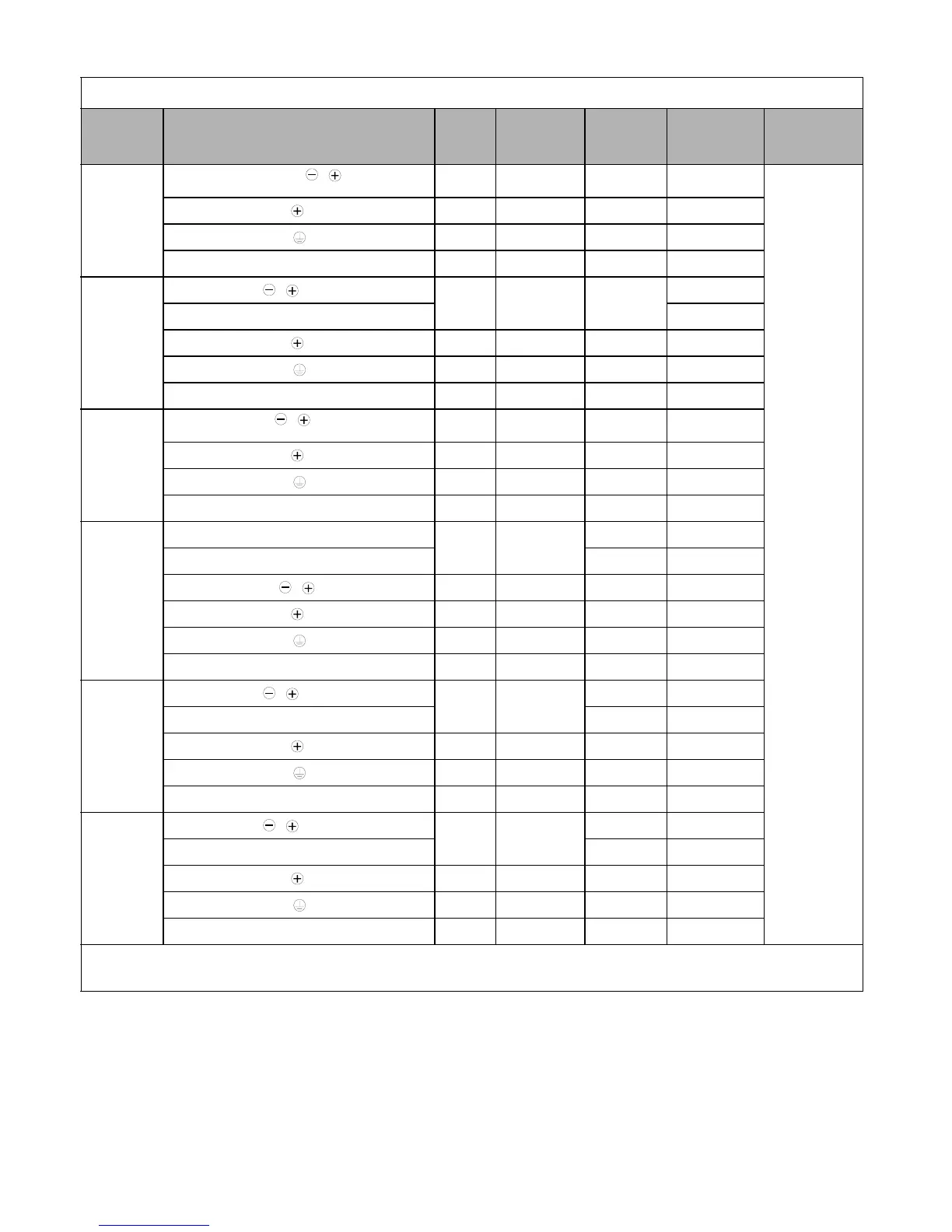
*1 Wire size range provided for Drives using insulated screw-type terminal blocks. All other models require the use of UL listed connectors. Refer to Table 2.3.
*2 Recommended wire sizes are based on the normal duty (ND) current ratings and NEC Article 310 Table 310.16, 75 degree Celsius copper or equivalent.
When sizing wiring based on the heavy duty (HD) current ratings, consult NEC Article 430 and any other applicable codes.
Table 2.1 208-240Vac Wire Sizes and Connector Specifications (Continued)
Drive Model
CIMR-F7U
Terminal Symbol
Terminal
Screws
Clamping
Torque
lb. in.
(N•m)
Possible Wire
Sizes AWG
(mm
2
)
*1
Recommended
Wire Size AWG
(mm
2
)
*2
Wire
Type
Email: Sales@aotewell.com