Digital Operator 3 - 8
Operation Menu (-DRIVE-)
This menu is used for setting the frequency reference (Local Mode) or monitoring values such as output frequency and output
current. It is also used for displaying the fault history and the fault traces. The Drive must be in this menu in order to run. See
parameter b1-08 (Run Command Selection During Program).
U1 Monitor List
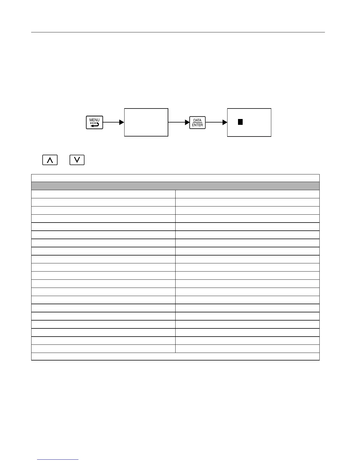
Follow the key operations below (Fig 3.3) to access the Operation Menu:
Fig 3.3 U1 Monitor List Access Procedure
Use and keys to scroll through the U1 “Monitor” parameter list. See Appendix A for functional description.
Table 3.8 U1 Monitor List
Monitors
U1-01 Frequency Reference U1-21 ASR Input
U1-02 Output Frequency U1-22 ASR Output
U1-03 Output Current U1-24 PI Feedback Value
U1-04 Control Method U1-25 DI-16 H2 Input Status
U1-05 Motor Speed U1-26 Output Voltage Reference (Vq)
U1-06 Output Voltage U1-27 Output Voltage Reference (Vd)
U1-07 DC Bus Voltage U1-28 CPU Number
U1-08 Output Power U1-29 kWh (Lower 4 digits)
U1-09 Torque Reference U1-30 MWh (Upper 5 digits)
U1-10 Input Terminal Status U1-32 ACR(q) Output
U1-11 Output Terminal Status U1-33 ACR(d) Output
U1-12 Drive Operation Status U1-34 OPE Detected
U1-13 Cumulative Operation Time U1-35 Zero Servo Pulse Count
U1-14 Software Number U1-36 PID Input
U1-15 Terminal A1 Input Voltage U1-37 PID Output
U1-16 Terminal A2 Input Voltage U1-38 PID Setpoint
U1-17 Terminal A3 Input Voltage U1-39 Modbus Error Code
U1-18 Motor Secondary Current (Iq) U1-40 Cooling Fan Elapsed Time
U1-19 Motor Excitation Current (Id) U1-44 ASR Output with or without Filter
U1-20 Output Frequency after Soft-start U1-45 Feed Forward Control Output
Note: Some monitors are not available for all Control Modes (A1-02).
-DRIVE-
** Main Menu **
- - - - - - - - - - - - - -
Operation
-DRIVE- Rdy
Frequency Ref
U1-01= 0.00Hz
- - - - - - - - - - - - - - - - - - - -
U1-02= 0.00Hz
U1
03= 0.00A
x1
Email: Sales@aotewell.com