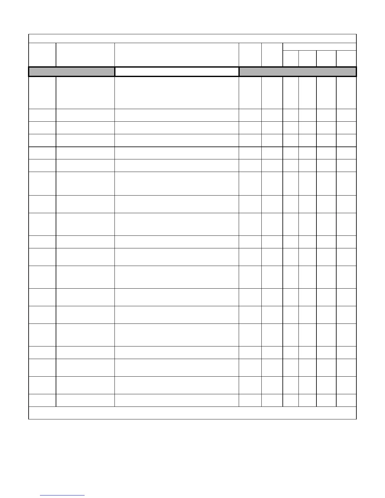
Parameters A - 7
PID Control
b5-01
PID Function Setting
PID Mode
This parameter determines the function of the PID control.
0: Disabled
1: D = Feedback
2: D = Feed-Forward
3: Freq. Ref. + PID output (D = Feedback)
4: Freq. Ref. + PID output (D = Feed-Forward)
0 to 4 0 A A A A
b5-02
Proportional Gain Setting
PID Gain
Sets the proportional gain of the PID controller.
0.00 to
25.00
1.00 A A A A
b5-03
Intregral Time Setting
PID I Time
Sets the integral time for the PID controller. A setting of zero
disables integral control.
0.0 to
360.0
1.0sec A A A A
b5-04
Intregral Limit Setting
PID I Limit
Sets the maximum output possible from the integrator. Set as a
percentage (%) of maximum frequency.
0.0 to
100.0
100.0% A A A A
b5-05
Derivative Time
PID D Time
Sets D control derivative time. A setting of 0.00 disables derivative
control.
0.00 to
10.00
0.00sec A A A A
b5-06
PID Output Limit
PID Limit
Sets the maximum output possible from the entire PID controller.
Set as a percentage (%) of maximum frequency.
0.00 to
100.0
100.0% A A A A
b5-07
PID Offset Adjustment
PID Offset
Sets the amount of offset of the output of the PID controller. Set as a
percentage (%) of maximum frequency.
The offset is summed with the PID output. This can be used to
artificially kick-start a slow starting PID loop.
–100.0 to
+100.0
0.0% A A A A
b5-08
PID Primary Delay Time
Constant
PID Delay Time
Sets the amount of time for the filter on the output of the PID
controller.
0.00 to
10.00
0.00sec A A A A
b5-09
PID Output Level
Selection
Output Level Sel
Determines whether the PID controller will be direct or reverse
acting.
0: Normal Output
1: Reverse Output
0 to 1 0 A A A A
b5-10
PID Output Gain Setting
Output Gain
Sets the output gain of the PID controller.
0.0 to
25.0
1.0 A A A A
b5-11
PID Output Reverse
Selection
Output Rev Sel
0: 0 limit (when PID output goes negative, Drive stops). 0 limit is
automatic when reverse prohibit is selected using b1-04.
1: Reverse (when PID goes negative, Drive reverses).
0 to 1 0 A A A A
b5-12
PI
D Feedback Reference
Missing Detection
Selection
Fb los Det Sel
0: Disabled
1: Alarm
2: Fault
0 to 2 0 A A A A
b5-13
PID Feedback Loss
Detection Level
Fb los Det Lvl
Sets the PID feedback loss detection level as a percentage (%) of
maximum frequency (E1-04).
0 to 100 0% A A A A
b5-14
PID Feedback Loss
Detection Time
Fb los Det Time
Sets the PID feedback loss detection delay time in terms of
seconds.
0.0 to
25.5
1.0sec A A A A
b5-15
PID Sleep Function Start
Level
PID Sleep Level
Sets the sleep function start frequency.
Va ri es
by
Duty
Rating*
0.0Hz A A A A
b5-16
PID Sleep Delay Time
PID Sleep Time
Sets the sleep function delay time in terms of seconds.
0.0 to
25.5
0.0sec A A A A
b5-17
PID Accel/Decel Time
PID Acc/Dec Time
Applies an accel/decel time to the PID setpoint reference. The
Drive’s standard softstarter (C1-XX and S-curve) still affects the
output of the PID algorithm.
0.0 to
25.5
0.0sec A A A A
b5-18
PID Setpoint Selection
PID Setpoint Sel
Allows the b5-19 setting to be the PID target setpoint value.
0: Disabled
1: Enabled
0 to 1 0 A A A A
b5-19
PID Setpoint Value
PID Setpoint
Sets the PID target value. Use only when b5-18 = 1
0.0 to
100.0
0.0% A A A A
Denotes that parameter can be changed when the Drive is running.
* For Heavy Duty (HD) Rating (C6-01=0): Setting Range=0.0 to 300.0. For Normal Duty (ND) Rating (C6-01=2): Setting Range=0.0 to 400.0.
Table A.1 F7 Parameter List (Continued)
Parameter
No.
Parameter Name
Digital Operator Display
Description
Setting
Range
Factory
Setting
Control Method
V/F
V/F
w/PG
Open
Loop
Vector
Flux
Vector
Email: Sales@aotewell.com