Parameters A - 39
U1-12
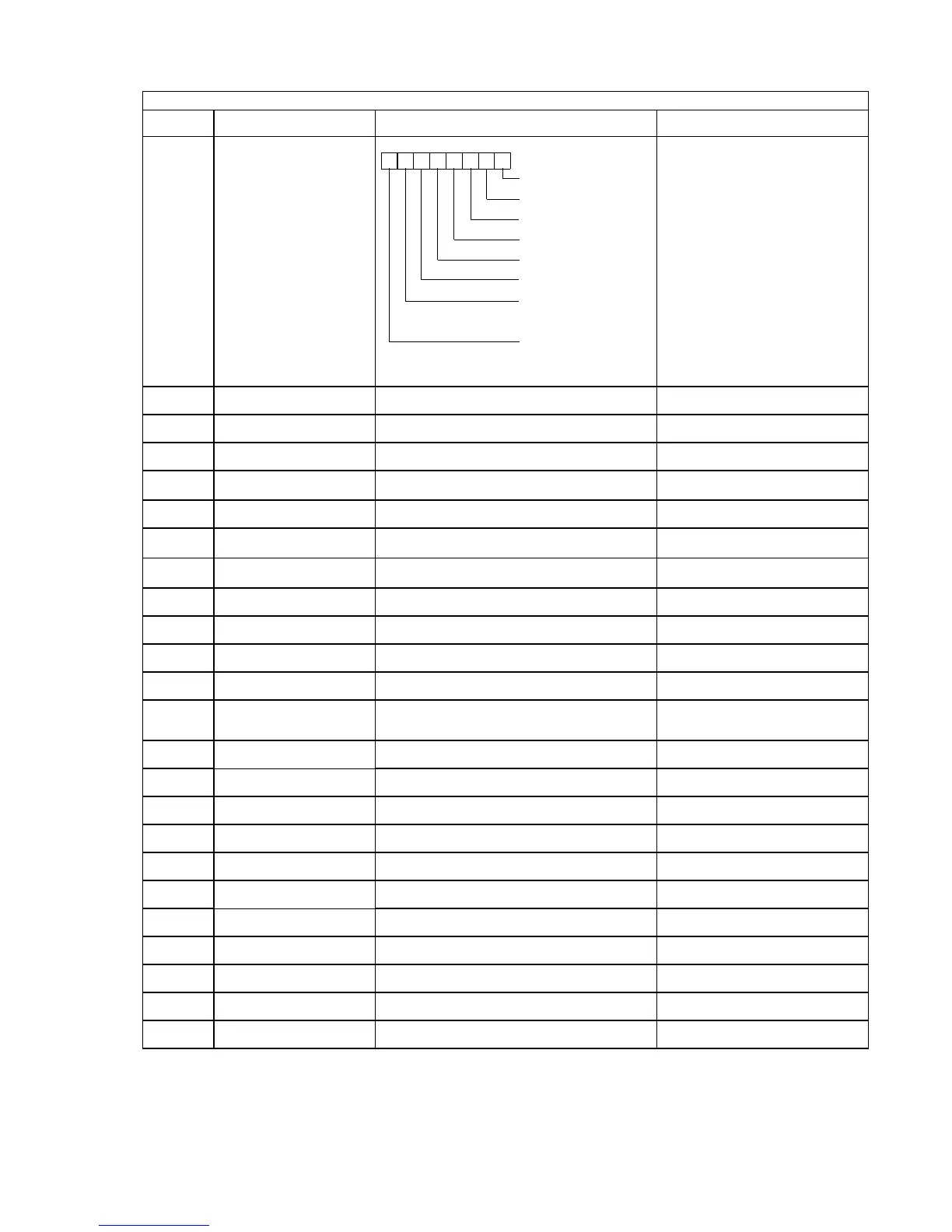
Drive Operation Status
Int Ctl Sts 1
Internal Drive status
-
U1-13
Cumulative Operation Time
Elapsed Time
Total operating or power-on time of the Drive. 1hr
U1-14
Software Number
FLASH ID
Last 5 digits of the Drive's software number. -
U1-15
Terminal A1 Input Voltage
Term A1 Level
Input voltage on Terminal A1, as a percentage of
±10Vdc.
0.1%
U1-16
Terminal A2 Input Voltage
Term A2 level
Displays the input current (or voltage) on Terminal A2, as a
percentage of
±10Vdc.
0.1%
U1-17
Terminal A3 Input Voltage
Term A3 level
Input voltage on Terminal A3, as a percentage of
±10Vdc.
0.1%
U1-18
Motor Secondary Current (I
q
)
Mot SEC Current
Current being used by the motor to produce torque (I
q
).
0.1%
U1-19
Motor Excitation Current (I
d
)
Mot EXC Current
Current being used by the motor for excitation (I
d
).
0.1%
U1-20
Output Frequency After Soft Start
SFS Output
Frequency reference (speed command) after the accel and
decel ramps and S-curve.
0.01Hz
U1-21
ASR Input
ASR Input
Input error to the speed control loop (ASR).
The maximum output frequency E1-04 corresponds to 100%.
0.01%
U1-22
ASR Output with Filter
ASR Output w Fil
Output from the speed control loop (ASR).
The motor rated secondary current corresponds to 100%.
0.01%
U1-24
PI Feedback Value
PID Feedback
Feedback signal level when PID control is used. 0.01%
U1-25
DI-16H2 Input Status
DI-16 Reference
Reference value from a DI-16H2 Digital Reference Card.
The value will be displayed in binary or BCD depending on
user constant F3-01.
Set by F3-01
U1-26
Output voltage reference (Vq)
Voltage Ref (Vq)
Internal voltage reference for motor secondary current control. 0.1Vac
U1-27
Output voltage reference (Vd)
Voltage Ref (Vd)
Internal voltage reference for motor excitation current control. 0.1Vac
U1-28
CPU Number
CPU ID
Control board hardware revision. -
U1-29
kWh
kWh Lo 4 Digits
Accumulated kilowatt-hours. 0.1kWh
U1-30
MWh
kWh Hi 5 Digits
Accumulated megawatt-hours. 1MWh
U1-32
ACR output of q axis
ACR(q) Output
Current control output value for the motor secondary current. 0.1%
U1-33
ACR output of d axis
ACR(d) Output
Current control output value for the motor excitation current. 0.1%
U1-34
First Parameter Causing an OPE
OPE Detected
Parameter number causing an "OPE" fault. -
U1-35
Zero Servo Pulse Count
Zero Servo Pulse
Number of PG pulses times 4 for the movement range when
stopped at zero servo.
1 pulse
U1-36
PID Input
PID Input
Input error to the PID regulator
(PID Setpoint - PID Feedback).
0.01%
U1-37
PID Output
PID Output
Output of the PID regulator as a percentage of maximum
frequency (E1-04).
0.01%
Table A.2 F7 Monitor List (Continued)
Parameter
No.
Parameter Name
Digital Operator Display
Description Display Units
1: During running
1: During zero speed
1: During reverse
1: During reset signal inpu
1: During speed agree
1: Drive operation ready
1: During fault detection
(Minor fault)
1: During fault detection
(Major fault)
0 0 0 0 0 0 0 0
Email: Sales@aotewell.com