Electrical Installation 2 - 7
4132
R/L1, S/L2, T/L3, , 1, R1/L11, S1/L21, T1/L33
M10
154.8 to 197.5
(17.6 to 22.5)
N/A
3/0 × 2P
(80 × 2P)
600Vac
UL Approved
vinyl-sheathed
or equivalent
U/T1, V/T2, W/T3 N/A
2/0 × 2P
(70 × 2P)
3
M8
77.4 to 95.0
(8.8 to 10.8)
N/A
Application
Dependent
M12
276.2 to 344.8
(31.4 to 39.2)
N/A
4/0
(100)
r/
l1, s200/l
2
200, s400/l
2
400 M4
11.4 to 12.3
(1.3 to 1.4)
N/A
16
(1.25)
4160
R/L1, S/L2, T/L3, , 1, R1/L11, S1/L21, T1/L33
M12
276.2 to 344.8
(31.4 to 39.2)
N/A
4/0 × 2P
(100 × 2P)
U/T1, V/T2, W/T3 N/A
3/0 × 2P
(80 × 2P)
3
M8
77.4 to 95.0
(8.8 to 10.8)
N/A
Application
Dependent
M12
276.2 to 344.8
(31.4 to 39.2)
N/A
1/0 × 2P
(60 × 2P)
r/
l1, s200/l
2
200, s400/l
2
400 M4
11.4 to 12.3
(1.3 to 1.4)
N/A
16
(1.25)
4185
R/L1, S/L2, T/L3,
U/T1, V/T2, W/T3, R1/L11, S1/L21, T1/L33
M16
693.9 to 867.4
(78.4 to 98.0)
N/A
300 x 2P
(150 x 2P)
, 1
N/A
600 X 2P
(325 X 2P)
3
N/A
Application
Dependent
N/A
3/0 x 2P
(80 x 2P)
r/
l1, s200/l
2
200, s400/l
2
400 M4
11.4 to 12.3
(1.3 to 1.4)
N/A
16
(1.25)
4220
R/L1, S/L2, T/L3, R1/L11, S1/L21, T1/L33
M16
693.9 to 867.4
(78.4 to 98.0)
N/A
500 x 2P
(325 x 2P)
U/T1, V/T2, W/T3 N/A
400 x 2P
(200 x 2P)
, 1
N/A
250 X 4P
(125 X 4P)
3
N/A
Application
Dependent
N/A
250 x 2P
(125 x 2P)
r/
l1, s200/l
2
200, s400/l
2
400
M4
11.4 to 12.3
(1.3 to 1.4)
N/A
16
(1.25)
4300
R/L1, S/L2, T/L3, R1/L11, S1/L21, T1/L33
M16
693.9 to 867.4
(78.4 to 98.0)
N/A
250 x 4P
(125 x 4P)
U/T1, V/T2, W/T3 N/A
4/0 x 4P
(100 x 4P)
, 1
N/A
400 X 4P
(200 X 4P)
3
N/A
Application
Dependent
N/A
400 x 2P
(203 x 2P)
r/
l1, s200/l
2
200, s400/l
2
400
M4
11.4 to 12.3
(1.3 to 1.4)
N/A
16
(1.25)
*1 Wire size range provided for Drives using insulated screw-type terminal blocks. All other models require the use of UL listed connectors. Refer to Table 2.3.
*2 Recommended wire sizes are based on the normal duty (ND) current ratings and NEC Article 310 Table 310.16, 75 Degree Celsius copper or
equivalent. When sizing wiring based on the heavy duty (HD) current ratings, consult NEC Article 430 and any other applicable codes.
IMPORTANT
Determine the wire size for the main circuit so that line voltage drop is within 2% of the rated voltage. Line
voltage drop is calculated as follows:
Line voltage drop (V) =
x wire resistance (Ω/km) x wire length (m) x current (A) x 10
-3
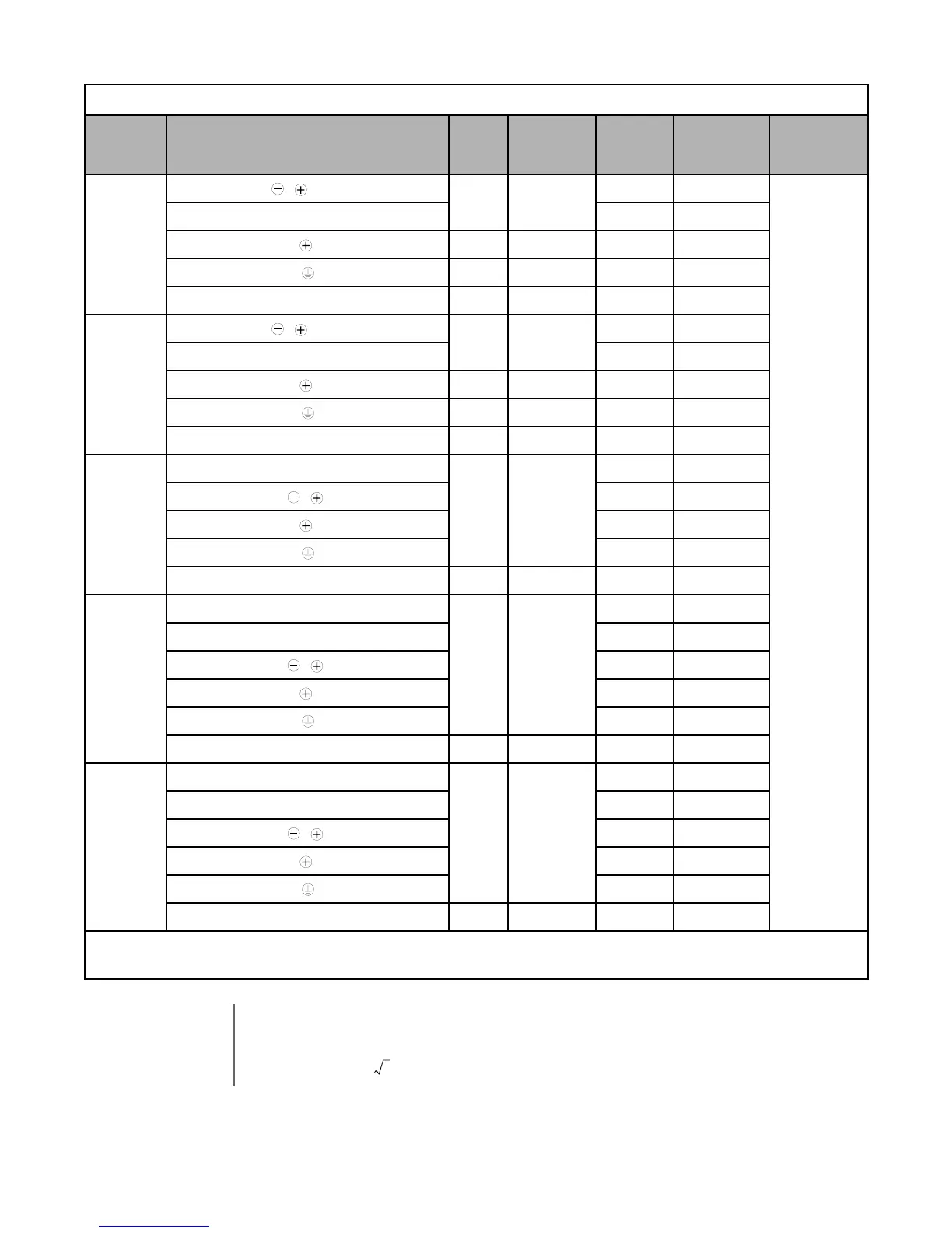
Table 2.2 480Vac Wire Sizes and Connector Specifications (Continued)
Drive Model
CIMR-F7U
Terminal Symbol
Terminal
Screws
Clamping
Torq ue
lb. in.
(N•m)
Possible Wire
Sizes AWG
(mm
2
)
*
1
Recommended
Wire Size AWG
(mm
2
)
*2
Wire Type
3
Email: Sales@aotewell.com