Start-Up 4 - 13
Parameter
No.
Parameter Name
Digital Operator Display
Description
Setting
Range
Factory
Setting
Control Method
V/F
V/F
w/
PG
OLV FV
E1-01
Input Voltage Setting
Input Voltage
Set to the nominal voltage of the incoming line, sets maximum/
base voltage used by preset V/F patterns (E1-03 = 0 to E), adjusts
the levels of Drive protective features (i.e. Overvoltage, braking
resistor turn-on, stall prevention, etc.).
155 to
255.0
(240V)
310 to
510.0
(480V)
240V
480V
QQ Q Q
E1-03
V/F Pattern Selection
V/F Selection
Set to the type of motor being used and the type of application.
The Drive operates utilizing a set V/F pattern to determine the
appropriate output voltage level for each commanded speed. There
are 15 different preset V/F patterns to select from (E1-03 = 0 to E)
with varying voltage profiles, base levels (base level = frequency
at which maximum voltage is reached), and maximum frequencies.
There are also settings for Custom V/F patterns that will use the
settings of parameters E1-04 through E1-13. E1-03 = F selects a
custom V/F pattern with an upper voltage limit and E1-03 = FF selects
a custom V/F pattern without an upper voltage limit.
0: 50Hz
1: 60Hz
2: 60Hz (50Hz Base)
3: 72Hz (60Hz Base)
4: 50Hz VT1
5: 50Hz VT2
6: 60Hz VT1
7: 60Hz VT2
8: 50Hz HST1
9: 50Hz HST2
A: 60Hz HST1
B: 60Hz HST2
C: 90Hz (60Hz Base)
D: 120Hz (60Hz Base)
E: 180Hz (60Hz Base)
F: Custom V/F
FF:Custom w/o limit
0 to FF F Q Q - -
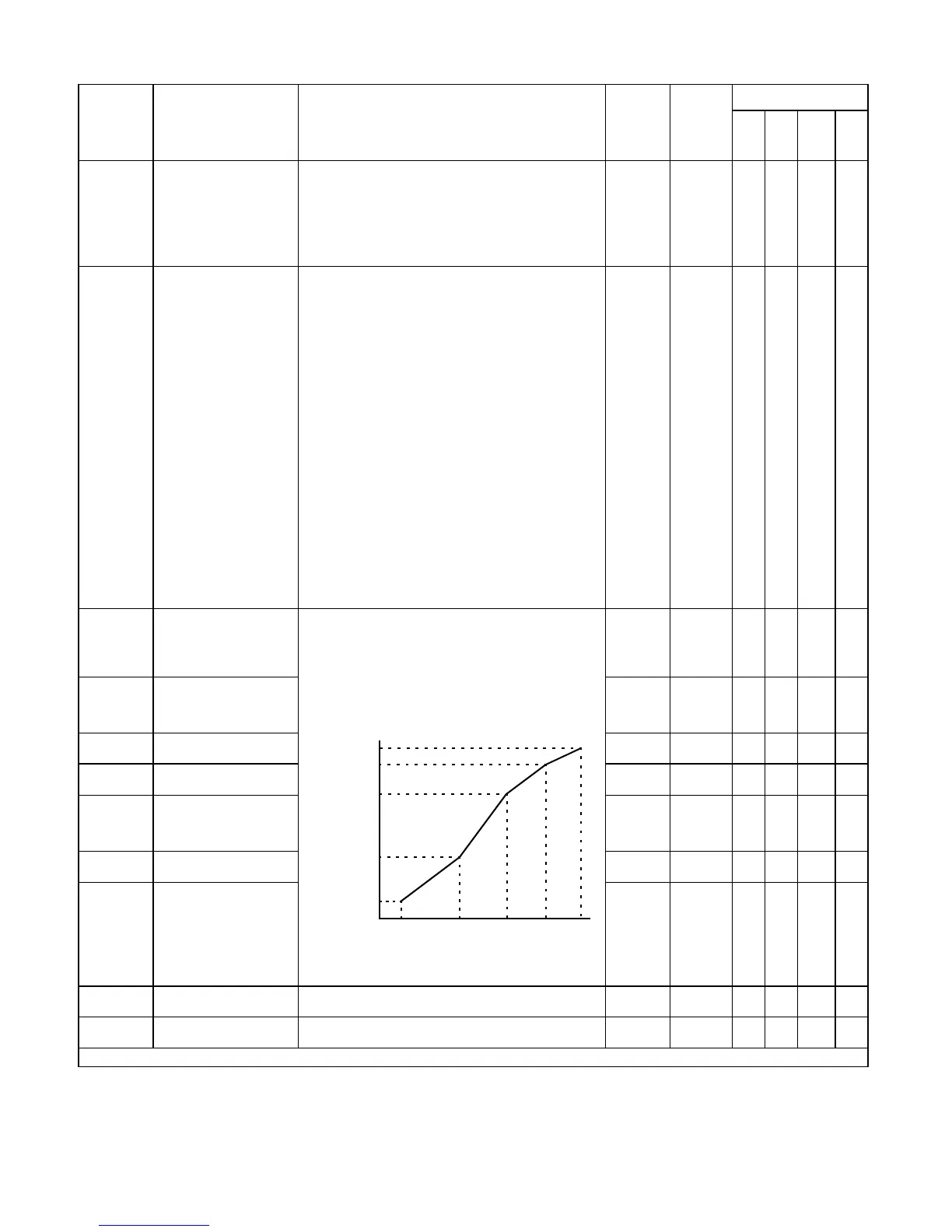
E1-04
Maximum Output Frequency
Max Frequency
These parameters are only applicable when V/F Pattern Selection
is set to Custom (E1-03 = F or FF). To set V/F characteristics in a
straight line, set the same values for E1-07 and E1-09. In this case,
the setting for E1-08 will be disregarded. Always ensure that the
four frequencies are set in the following manner:
E1-04 ≥ E1-12 ≥ E1-06 > E1-07 ≥ E1-09
E2-04 is automatically set during Auto-Tuning.
HD: 40.0
to 300.0
ND2: 40.0
to 400.0
60.0Hz Q Q Q Q
E1-05
Maximum Output Voltage
Max Voltage
0 to 255.0
(240V)
0 to 510.0
(480V)
240V
480V
QQ Q Q
E1-06
Base Frequency
Base Frequency
0.0 to
200.0
60.0Hz Q Q Q Q
E1-09
Minimum Output Frequency
Min Frequency
0.0 to
200.0
1.5Hz Q Q Q A
E1-13
Base Voltage
B
ase Voltage
0 to 255.0
(240V)
0 to 510.0
(480V)
0.0VAC A A Q Q
E2-01
Motor Rated Current
Motor Rated FLA
Varies by
kVA
Varies by
kVA
QQ Q Q
E2-04
Number of Motor Poles
Number of Poles
2 to 48 4 - Q - Q
E2-11
Motor Rated Output
Motor Rated Power
Set to the motor rated power in KW.
This value is automatically set during Auto-Tuning.
0.00 to
650.00
Varies by
kVA
QQ Q Q
F1-01
PG Parameter
PG Pulse/Rev
Sets the number of pulses per revolution of the encoder (pulse
generator). This value is automatically set during Auto-Tuning.
0 to 60000 1024 - Q - Q
Denotes that parameter can be changed when the Drive is running.
Output voltage (V)
Frequency (Hz)
E1-09 E1-07 E1-06 E1-11 E1-04
E1-05
E1-12
E1-13
E1-08
E1-10
Email: Sales@aotewell.com