10 Drive Start-Up Procedure
YASKAWA TOEPC7106171FD FP605 DRIVE INSTALLATION & PRIMARY OPERATION 67
NOTICE
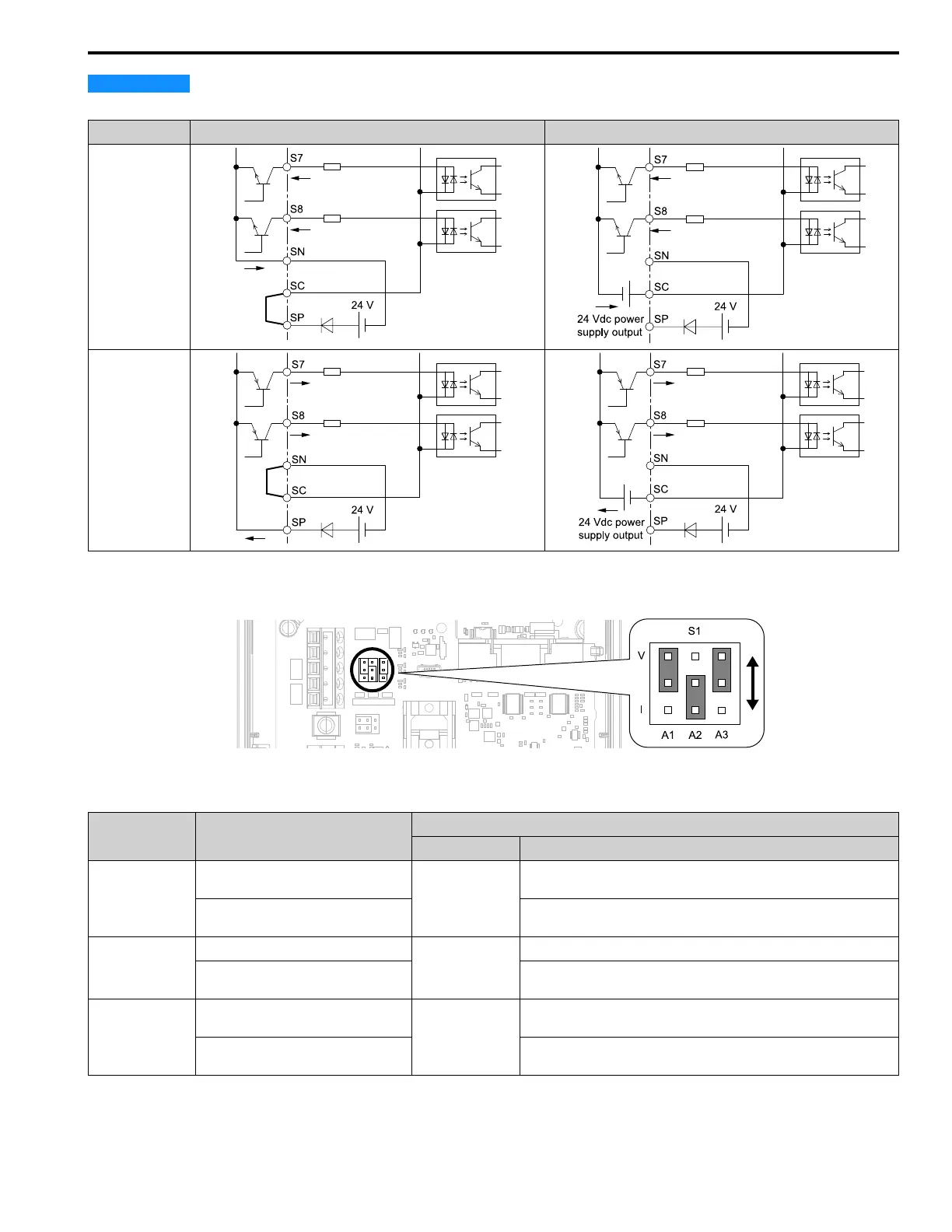
Damage to Equipment. Do not close the circuit between terminals SP-SN. If you close the circuits between
terminals SC-SP and terminals SC-SN at the same time, it will cause damage to the drive.
Mode Internal Power Supply (Terminal SN-SP) External 24 V power supply
Sinking Mode (NPN)
Sourcing Mode
(PNP)
■ Set Input Signals for MFAI Terminals A1 to A3
Use terminals A1 to A3 to input a voltage or a current signal. Set the signal type as shown in Table 10.9.
Figure 10.9 Location of Jumper Switch S1
Table 10.9 MFAI Terminals A1 to A3 Signal Settings
Terminal Types of Input Signals
Parameter
No. Signal Level
A1
Voltage input
(Default)
H3-01
0: 0 V to 10 V/0% to 100% (input impedance: 20 kΩ)
Current input
2: 4 mA to 20 mA/0% to 100% (input impedance: 250 Ω)
3: 0 mA to 20 mA/0% to 100% (input impedance: 250 Ω)
A2
Voltage input
H3-09
0: 0 V to 10 V/0% to 100% (input impedance: 20 kΩ)
Current input
(Default)
2: 4 mA to 20 mA/0% to 100% (input impedance: 250 Ω)
3: 0 mA to 20 mA/0% to 100% (input impedance: 250 Ω)
A3
Voltage input
(Default)
H3-05
0: 0 V to 10 V/0% to 100% (input impedance: 20 kΩ)
Current input
2: 4 mA to 20 mA/0% to 100% (input impedance: 250 Ω)
3: 0 mA to 20 mA/0% to 100% (input impedance: 250 Ω)
 Loading...


