3 Mechanical Installation
24 YASKAWA TOEPC71061779B GA800 Drive Installation Manual
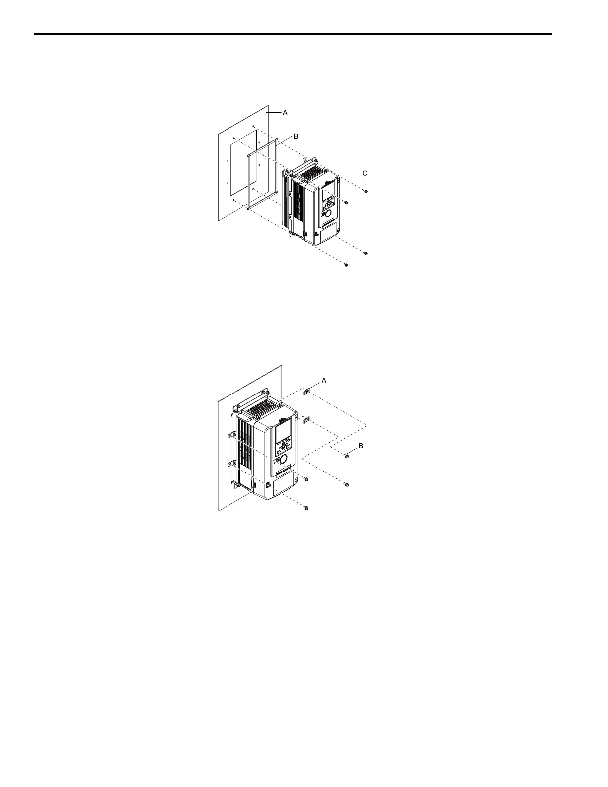
1. Install the drive in the cut opening of the enclosure panel and use screws to safety it to the enclosure panel.
Tighten the screws to a correct tightening torque:
• M5 screws: 1.96 N∙m to 2.53 N∙m (17.35 in∙lb to 22.39 in∙lb)
• M6 screws: 3.92 N∙m to 4.90 N∙m (34.70 in∙lb to 43.37 in∙lb)
A - Enclosure panel
B - Gasket
C - M5 screws or M6 screws
Figure 3.15 Install the Drive into the Opening of the Enclosure Panel
2. Use screws to safety the panel supports.
Tighten the screws to a correct tightening torque:
• M5 screws: 1.96 N∙m to 2.53 N∙m (17.35 in∙lb to 22.39 in∙lb)
A - Panel supports B - M5 screws
■ Install the Drive (Procedure B)
Cut an opening in the enclosure panel before you install the attachment. Refer to Panel Cut-Out Dimensions (IP55/UL
Type 12 Heatsink External Mounting) on page 18 for more information.

 Loading...


