Technical Tip: iQPump1000 Setup Procedure for Use with Seametrics AG2000 Flow Meter
TN.iQp.04 ©2016 - Yaskawa America, Inc.
Revision 1 - 2016-04 Page 5 of 10
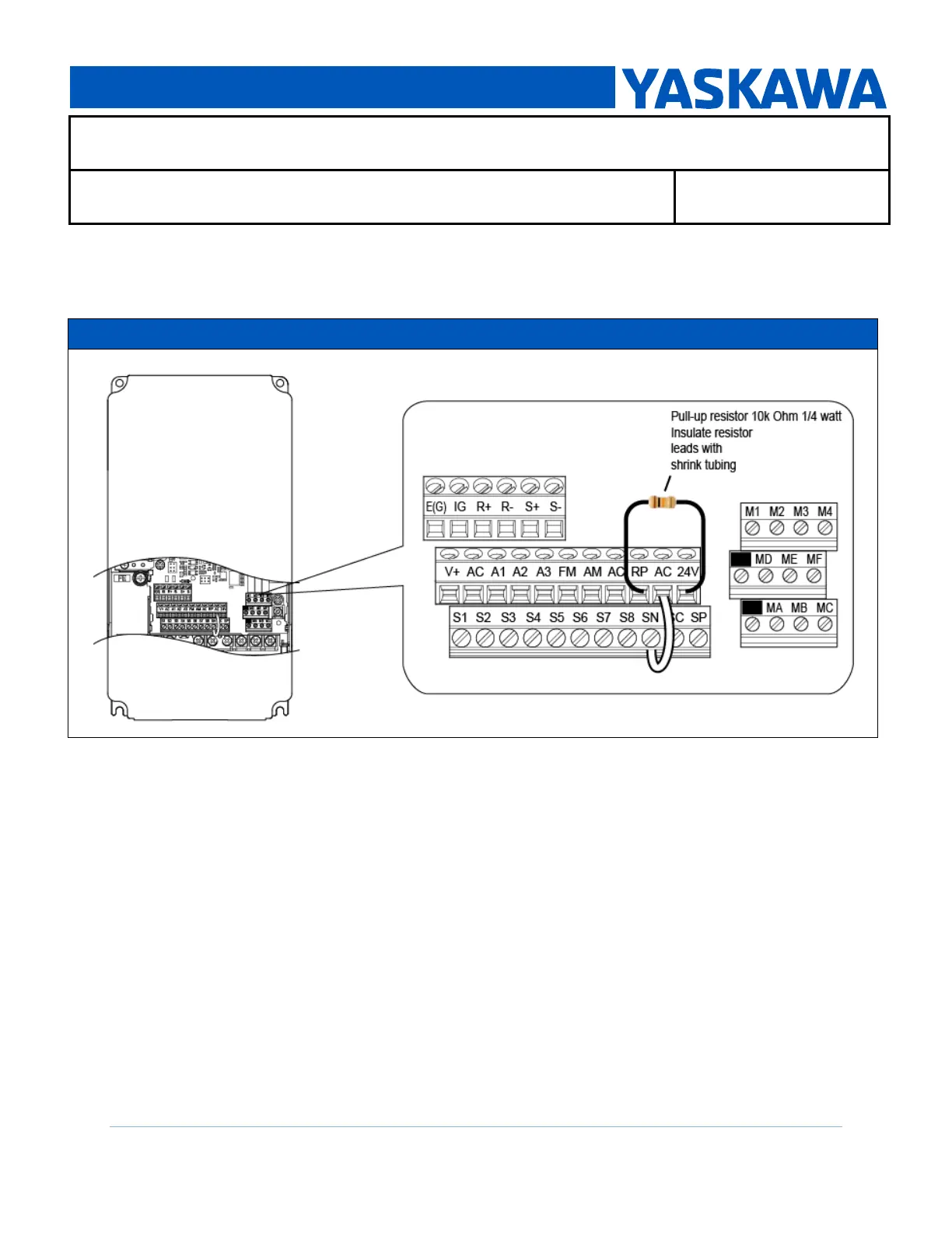
1.2 Install a pull-up resistor at iQpump1000 I/O terminals RP and 24V as shown in Figure 3.
The pulse train output of the Seametrics AG2000 Flow Meter is a “sinking” type that requires a
customer-supplied 10k Ohm resistor to condition the signal for the iQpump1000.
1.3 Re-install all covers on the iQpump1000.
1.4 Re-install the JVOP-183 digital operator on the iQpump1000 drive.
STEP 2 – VERIFY SIGNAL FROM FLOW METER TO IQPUMP1000
WARNING ! - Sudden Movement Hazard. Clear all personnel from the drive, motor, and machine
area before applying power. System may start unexpectedly upon application of power, causing
death or serious injury.
Preparation:
Prepare a digital multi-meter with a frequency counter function to measure a signal at
iQpump1000 I/O terminals AC to RP.
2.1 Energize the drive. The JVOP-183 digital operator should display: U1-01= 0.00 Hz.
2.2 Verify the pump is primed, and the system is prepared to receive flow.
Figure 3: iQpump1000 Control Terminal Arrangement with Pull-up Resistor Installed

 Loading...


