3 Electrical Installation
TOEP C710606 27 J1000 Quick Start Guide 15
ENGLISH
Main Circuit Terminals
Control Circuit Terminals
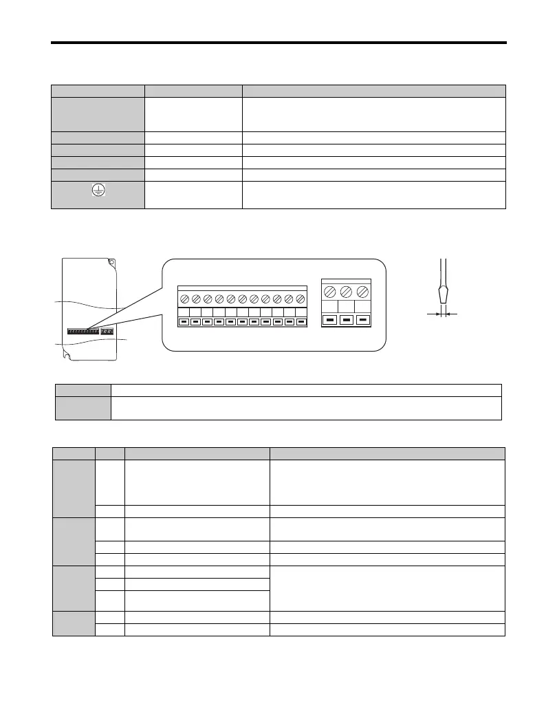
The figure below shows the control circuit terminal arrangement.
There are two DIP switches, S1 and S3, located on the control board
Control Circuit Terminal Functions
Terminal Type Function
R/L1, S/L2, T/L3
Main circuit power sup-
ply input
Connects line power to the drive.
Drives with single-phase 200 V input power use terminals R/L1
and S/L2 only (T/L3 is not used).
U/T1, V/T2, W/T3 Drive output Connects to the motor.
B1, B2 Braking resistor For connecting a braking resistor.
+1, +2 DC reactor connection Linked at shipment. Remove the link to install a DC choke.
+1, – DC power supply input For connecting a DC power supply.
(2 terminals)
Ground Terminal
For 200 V class: Ground with 100 Ω or less
For 400 V class: Ground with 10 Ω or less
SW1 Switches analog input A1 between voltage and current input
SW3
Used to select sourcing (PNP)/sinking (NPN, default) mode for the digital inputs (PNP requires
external 24 Vdc power supply)
Type No. Terminal Name (Signal) Function (Signal Level), Default Setting
Multi-
Function
Digital
Inputs
S1
to
S5
Multi-function digital input 1 to 5
Photocoupler inputs, 24 Vdc, 8 mA
Note: Drive preset to sinking mode (NPN). When using
source mode, set DIP switch S3 to “SOURCE” and use an
external 24 Vdc (±10%) power supply.
SC Multi-function input common Sequence common
Analog
Input
A1 Analog input
0 to +10 Vdc (20 kΩ) resolution 1/1000
0/4 to 20 mA (250 Ω) resolution: 1/500
+V Analog input power supply +10.5 V (max allowable current 20 mA)
AC Frequency reference common 0 V
Multi-
Function
Relay
Output
MA N.O. (fault)
Digital relay output
30 Vdc, 10 mA to 1 A
250 Vac, 10 mA to 1 A
MB N.C. output (fault)
MC Digital output common
Monitor
Output
AM Analog monitor output 0 to 10 Vdc (2 mA or less), Resolution: 1/256 (8 bit)
AC Monitor common 0 V
S1 S2 S3 S4 S5 SC A1 +V AC AM AC
MCMBMA
Use a straght-edge screwdriver
with a blade width of max 2.5 mm
and a thickness of max 0.6 mm to
release the terminals

 Loading...


