22 TOEP C710606 27 J1000 Quick Start Guide
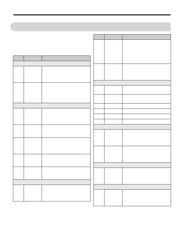
6 Parameter Table
6 Parameter Table
This parameter table shows the most impor-
tant parameters. Default settings are bold
type. Refer to the instruction manual for a
complete list of parameters.
Par. Name Description
Initialization Parameters
A1-01
Access
Level
Selection
Selects which parameters are
accessible via the digital operator.
0:Operation only
2:Advanced Access Level
A1-03
Initialize
Parameters
Resets all parameters to default.
(returns to 0 after initialization)
0000: No Initialize
2220: 2-Wire Initialization
3330: 3-Wire Initialization
Operation Mode Selection
b1-01
Frequency
Reference
Selection
0:Operator - d1- values
1:Analog input A1
2:Serial Comm.option
3:Potentiometer Option
b1-02
Run
Command
Selection
0:Operator - RUN and STOP keys
1:Terminals - Digital Inputs
2:Serial Comm.option
b1-03
Stopping
Method
Selection
Selects the stopping method when
the run command is removed.
0:Ramp to Stop
1:Coast to Stop
b1-04
Reverse
Operation
Selection
0:Reverse enabled
1:Reverse prohibited
b1-14
Phase Order
Selection
Switches the output phase order.
0:Standard
1:Switch phase order
DC Injection Braking
b2-02
DC
Injection
Braking
Current
Sets the DC Injection Braking cur-
rent as a percentage of the drive
rated current.
b2-03
DC Inj.
Braking
Time/DC
Excitation
Time at
Start
Sets the time of DC Injection Brak-
ing at start in units of 0.01 seconds.
Disabled when set to 0.00 seconds.
b2-04
DC Inj.
Braking
Time at
Stop
Sets the DC Injection Braking time
at stop. Disabled when set to 0.00
seconds.
Acceleration/ Deceleration
C1-01
Accel
Time 1
Sets the acceleration time 1 from 0
to the max. output frequency.
C1-02
Decel
Time 1
Sets the deceleration time 1 from
the max. output frequency to 0.
C2-01 S-Curve 1 S-curve at acceleration start.
C2-02 S-Curve 2 S-curve at acceleration end.
C2-03 S-Curve 3 S-curve at deceleration start.
C2-04 S-Curve 4 S-curve at deceleration end.
Slip Compensation
C3-01
Slip Com-
pensation
Gain
• Increase if the speed is lower than
the frequency reference
• Decrease if the speed is higher
than the frequency reference.
C3-02
Slip Com-
pensation
Delay Time
• Decrease the setting when the slip
compensation is too slow.
• Increase the setting when the
speed is not stable.
Torque Compensation
C4-01
Torque
Compensa-
tion Gain
• Increase this setting when the
torque response is slow
• Decrease this setting when speed/
torque oscillations occur.
Duty Mode and Carrier Frequency
C6-01
Normal/
Heavy Duty
Selection
0: Heavy Duty (HD)
Constant torque applications
1:Normal Duty (ND)
Variable torque application
Par. Name Description

 Loading...


