ENGLISH
3 Electrical Installation
TOEP C710606 27 J1000 Quick Start Guide 11
3 Electrical Installation
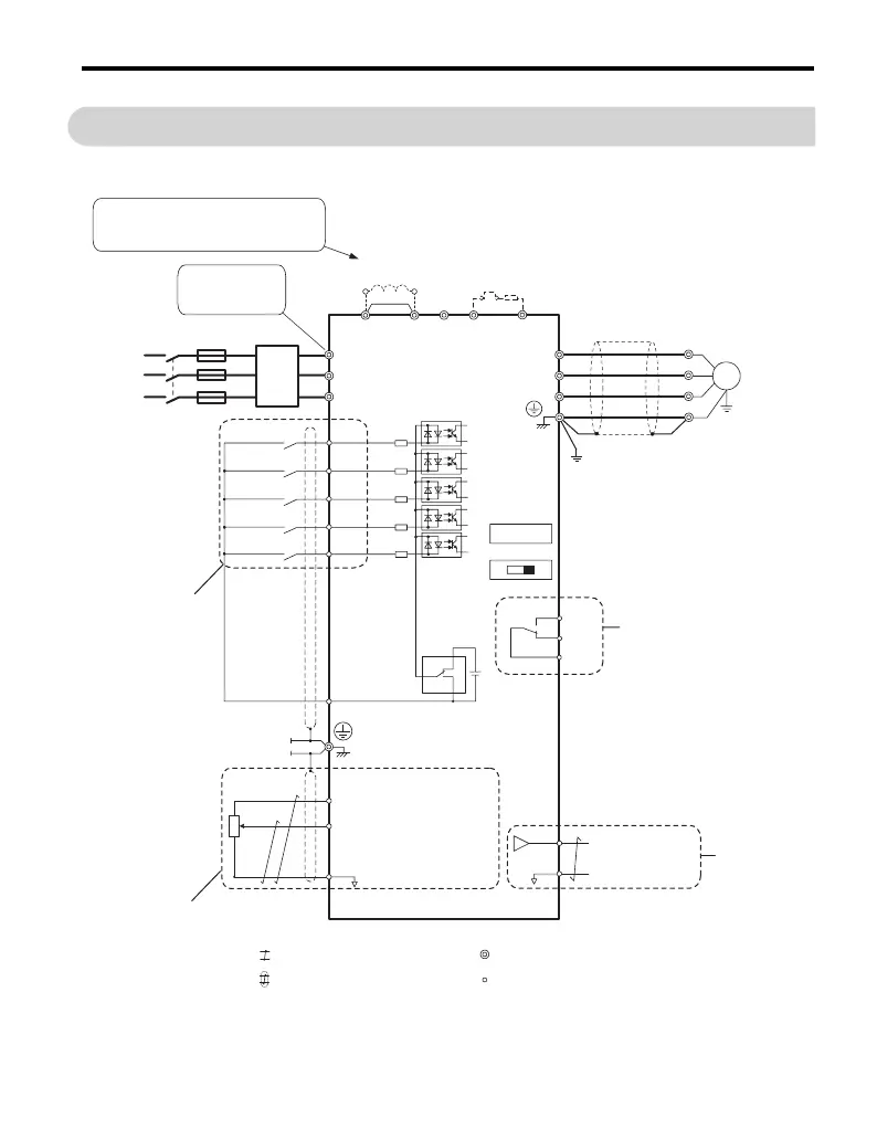
The figure below shows the main and control circuit wiring.
R/L1
S/L2
T/L3
S1
S2
S3
S4
S5
B1+1
-
+2 B2
L1
L2
L3
U/T1
V/T2
W/T3
+24
V
SINK
SOURCE
MA
MB
MC
+24 V 8 mA
M
U
V
W
SC
AM
AC
+V
A1
AC
2 kΩ
DC reactor
(option)
For 1-phase
power supply use
R/L1 and S/L2
Terminals marked -,+1,+2,B1,B2 are for
connecting an option. Do not wire AC
power lines to these terminals.
Filter
Fuses
Main
Switch
Forward/Stop
Reverse/Stop
External Fault
Fault Reset
Multi-speed 1
Multi-function
digital inputs
(default setting)
Link
Thermal
relay
Braking
resistor
(option)
J1000
Ground
Multi-function relay output
250 Vac / 30 Vdc (10 mA to 1A)
(default setting)
Fault
DIP
switch S3
Shielded ground
terminal
Analog input power supply
+10.5 Vdc, max. 20 mA
Analog input
Monitor output
(default setting)
Analog output
0 to +10 Vdc (2mA)
(Output frequency)
Shielded
Cable
Symbols:
Use twisted pair cables
Use shielded twisted pair cables
Indicates a main circuit terminal
Indicates a control circuit terminal.
Power
Supply
DIP switch S1
Option unit
connector
IV
Analog input
0 to 10 V (20 kΩ) or
0/4 to 20 mA (250 Ω)