5 Installation Procedure
34 YASKAWA ELECTRIC TOBP C730600 75B YASKAWA AC Drive Option PG-B3 Installation Manual
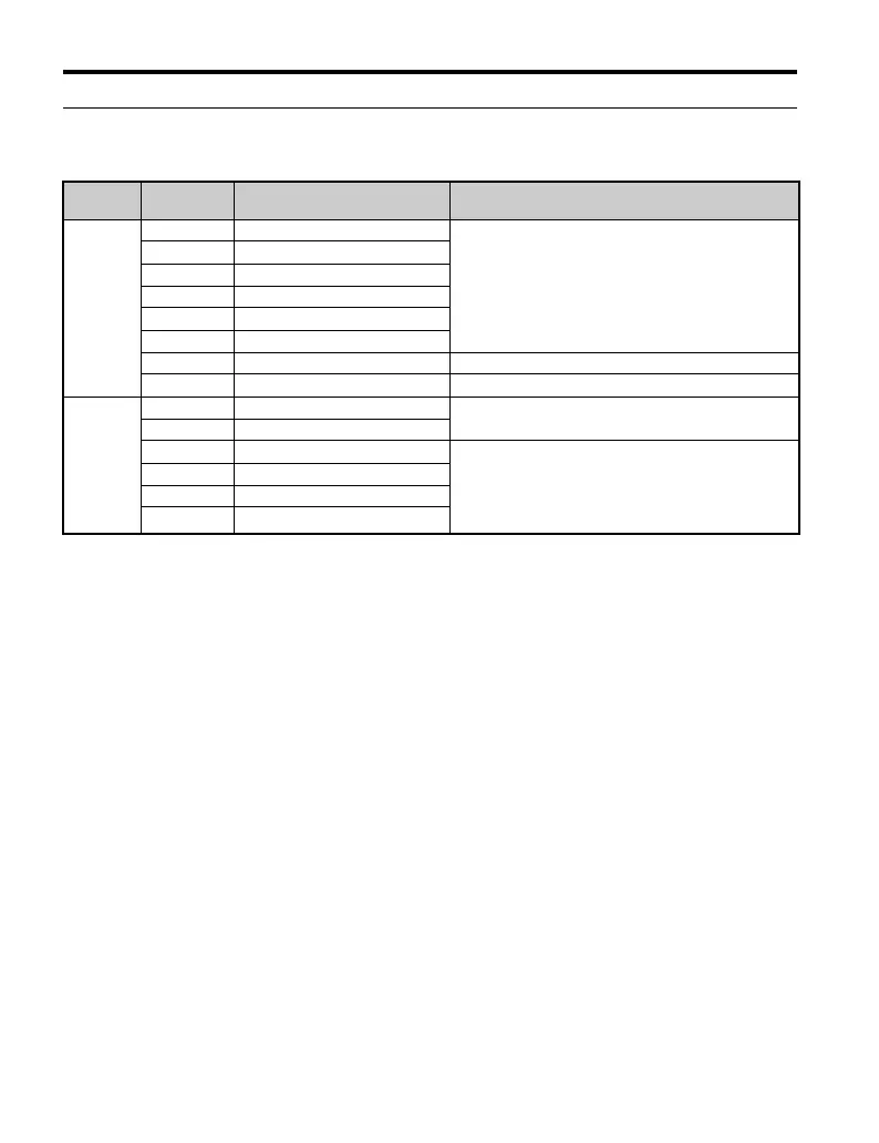
u Terminal Functions
Table 9
Option Terminal Functions
Terminal
Block
Terminal Function Description
TB1
<1> A separate UL-listed class 2 power supply is necessary when the PG requires more than 200 mA to operate.
A+ A+ pulse signal input
• Pulse signal inputs from the PG.
• Signal inputs from complementary and
open-collector outputs
• Signal level
H level: 8 to 12 V
L level: 2.0 V or less
A– A– inverse pulse input
B+ B+ pulse signal input
B– B– inverse pulse input
Z+ Z+ pulse signal input
Z– Z– inverse pulse input
SD NC pin (open) For use when cables shields should not be grounded
FE Ground Used for grounding shielded lines
TB2
IP PG power supply
• Output voltage: 12.0 V ± 5%
• Max output current: 200 mA
<1>
IG PG power supply common
AO A pulse monitor signal • Outputs the monitor signal for the A, B, and Z pulses
from the PG speed control card
• For open collector outputs from the option
• Max voltage: 24 V
• Max current: 30 mA
BO B pulse monitor signal
ZO Z pulse monitor signal
IG Monitor signal common
TOBP_C730600_75B_1_0_E.book 34 ページ 2017年2月17日 金曜日 午後3時2分