B.1 Σ-Series AC Servopack Gain Adjustment
375
B.1.2 Basic Rules for Gain Adjustment
1) The servo system comprises three feedback systems: position loop, speed loop, and
current loop. The response must increase from outer loop to inner loop (see Servo Sys-
tem Block Diagram, above). The response deteriorates and oscillates if this principle is
not obeyed.
The customer cannot adjust the current loop. Sufficient response is assured for the cur-
rent loop.
The customer can adjust the position loop gain and speed loop gain, as well as the speed
loop integration time constant and torque reference filter.
2) The position loop and speed loop must be adjusted to provide a balanced response.
In particular, if the position loop gain only is increased (adjustment with Cn-03 at the Ser-
vopack if position loop gain adjustment is not possible at the host controller), the speed
references oscillate and the result is increased, oscillating position control times.
If the position loop gain (or Cn-03) is increased, the speed loop gain (Cn-04) must be
similarly increased.
If the mechanical system starts to oscillate after the position loop gain and speed loop
gain are increased, do not increase the gains further.
3) The position loop gain should not normally be increased above the characteristic fre-
quency of the mechanical system.
For example, the harmonic gears used in an articulated robot form a structure with ex-
tremely poor rigidity and a characteristic frequency of approximately 10 to 20 Hz. This
type of machine allows a position loop gain of only 10 to 20 (1/sec).
Conversely, the characteristic frequency of a precision machine tool such as a chip
mounter or IC bonder exceeds 70 Hz, allowing a position loop gain exceeding 70 (1/sec)
for some machines.
Therefore, although the response of the servo system (controller, servo driver, motor, de-
tectors, etc.) is an important factor where good response is required, it is also important to
improve the rigidity of the mechanical system.
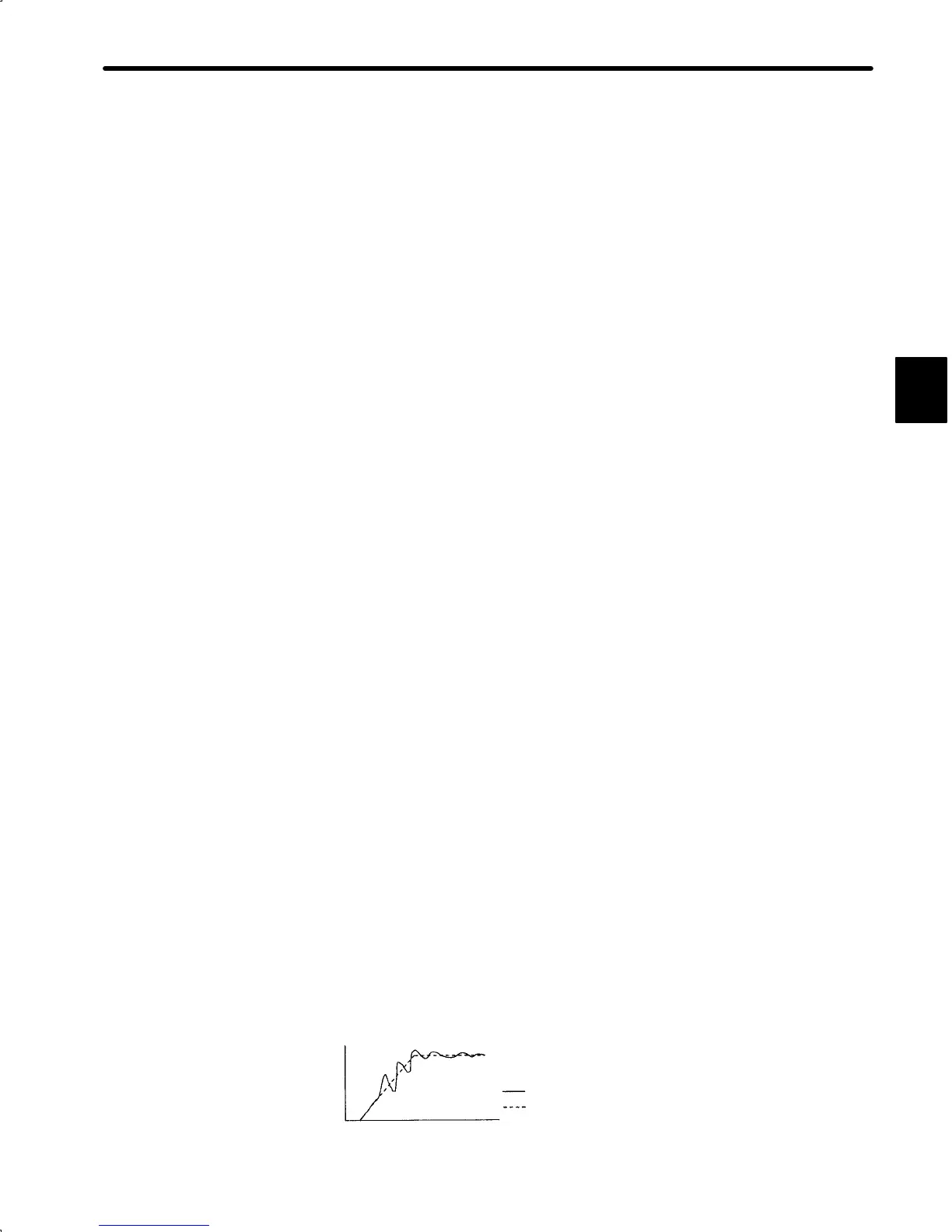
4) In cases where the position loop response is greater than or equal to the speed loop re-
sponse and linear acceleration or deceleration is attempted, the poor speed loop re-
sponse and follow-up cause an accumulation of position loop errors and result in in-
creased output of speed references from the position loop.
The motor moves faster and overshoots as a result of increased speed references, and
the position loop tends to decrease the speed references. However, the poor motor fol-
low-up due to the poor speed loop response results in oscillating speed references, as
shown in the diagram below.
If this problem occurs, reduce the position loop gain or increase the speed loop gain to
eliminate the speed reference oscillations.
Speed Reference Output with Unbalanced Position Loop Gain and Speed Loop
Gain
Speed
Reference
Time
Speed references actually output from controller
Speed references calculated in controller
B

 Loading...