4 Option Components
YASKAWA ELECTRIC TOBP C730600 89D YASKAWA AC Drive Option SI-EP3 Installation Manual 15
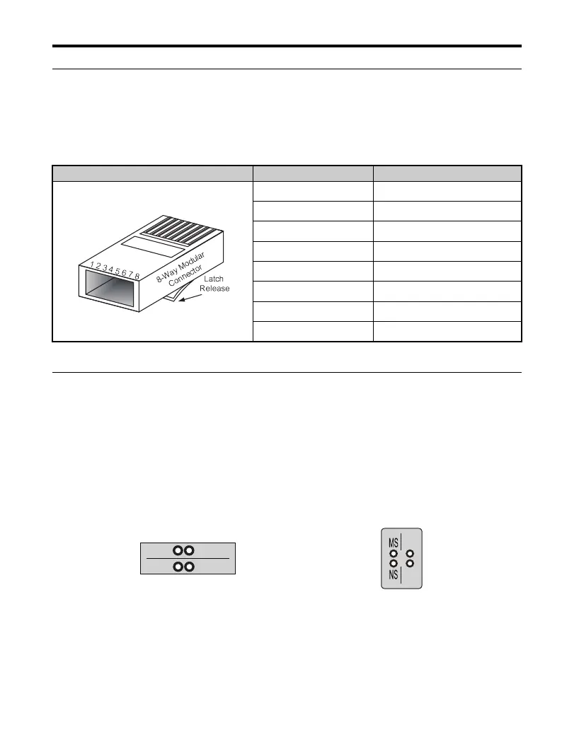
u Communication Modular Connector CN1 Port 1/Port 2
The communication modular connector CN1 on the option is a modular dual RJ45 female
connector designated port 1 and port 2. Port 1 and port 2 are the connection point for a
customer supplied male Ethernet network communication cable.
Table 3 Male 8-way Ethernet Modular Connector (Customer-Supplied)
u Option LED Display
The option has six LEDs:
Bi-color Status LEDs:
• Module status (MS) red/green
• Network status (NS) red/green
Ethernet LEDs (2 each):
• Network speed-10/100 yellow
• Link status and network activity-Link/Act green
Figure 3
Figure 3 Option LED Labels
Male EtherNet 8-Way Modular Connector Pin Description
1 (Pair 2) Transmit data (TXD) +
2 (Pair 2) Transmit data (TXD) -
3 (Pair 3) Receive data (RXD) +
4 (Pair 1) Not used
<1>
<1> Not used for 10 Mbps and 100 Mbps networks.
5 (Pair 1) Not used
<1>
6 (Pair 3) Receive data (RXD) -
7 (Pair 4) Not used
<1>
8 (Pair 4) Not used
<1>
1000-Series Label
GA500, GA700, and GA800 Label
GEM_PROFINET_IM_E_conditional.book 15 ページ 2019年2月21日 木曜日 午後3時37分

 Loading...


