n
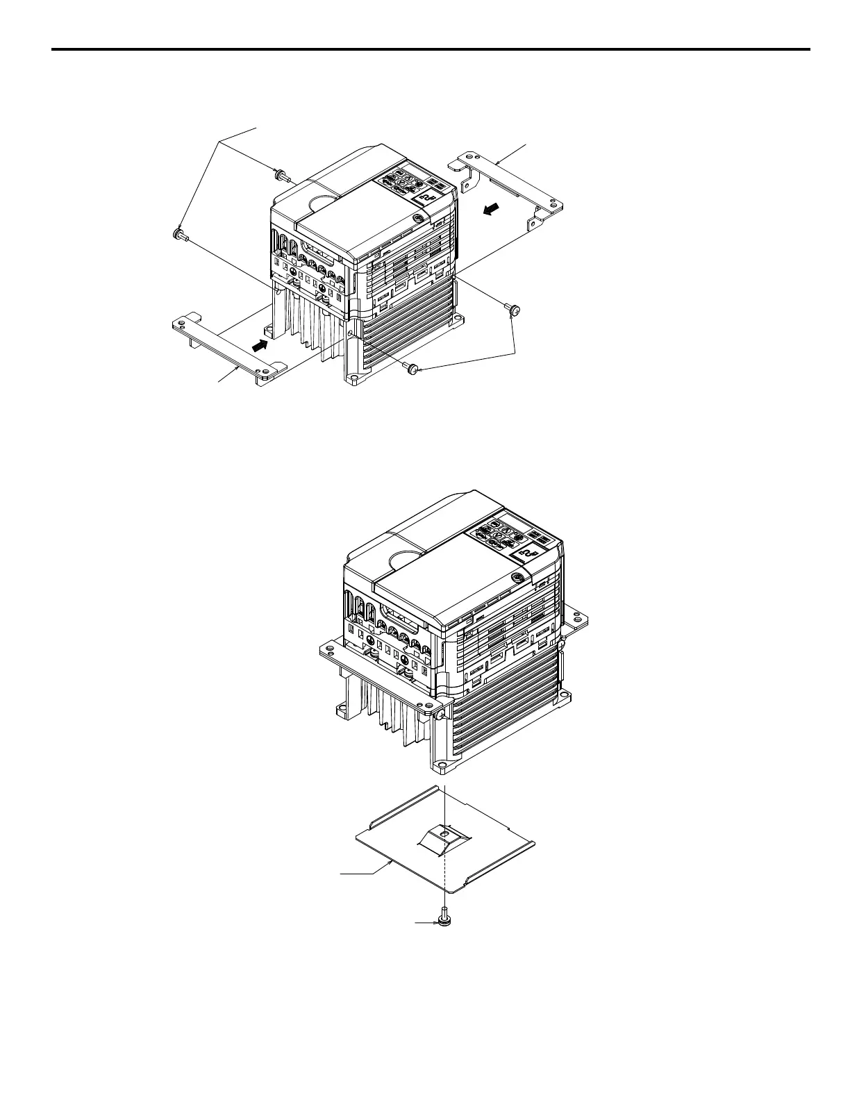
Procedure 3 (Enclosure: IP20)
1. Mount Attachment A (2 each) to the mounting holes on the side of the heatsink using the M4×10 pan-head screws.
Attachment A
M4 x 10 Pan-head Screws (x2)
Attachment A
M4 x 10 Pan-head Screws (x2)
Figure 5 Procedure 3 Diagram (Example Model CIMR-Vo2o0010)
n
Procedure 4 (Enclosure: IP20)
1. Mount the Convective Back Plate to the mounting holes on underside of the heatsink using M4×10 pan-head screws.
M4 x 10 Pan-head Screw
Convective
back plate
Figure 6 Procedure 4 Diagram (Example Model: CIMR-Vo2o0010)
5 Installation Procedure by Drive Model
YASKAWA V1000/J1000 AC Drive External Heatsink Kit Option Manual EZZ020568
15

 Loading...


